 Contents
List
Contents
ListHelpful ideas for setting up a small blacksmith's pneumatic forging hammer.
[Home] [Back to Air Hammers Links Page] [Striker STC-88 Air Hammer] [Fabricated Adjustable Throttle Stop] [Photos of STC088 Working] [ STC-88 Misc. Info ] [Additional new parts in 2010]
UPDATED November 5th, 2022. I am currently looking into getting some dies and other parts for sale again. This takes quite a bit of time to set up. First need to find someone that speaks english.
High-quality, open-die style (free form) pneumatic forging hammer for the blacksmith. Striker air hammers are made to (O.E.M.) original equipment manufacture standards- and the level of quality of these hammers becomes strikingly (sorry about the pun:) visible when comparing this hammer side by side with its competitors. The Striker power hammer shown here is my own and since the first day it ran, it requires little maintenance and always runs trouble-free.
Contents
List
Page Updates
November 8th, 2022. Oil recommendation section cleaned up. Some photos improved to show up better on modern high resolution computer monitors.
February 4th, 2011. Electrical troubleshooting section re-written, Tools for Air Hammers section has been completely re-written and improved.
January 30th, 2011. Latest NEWS: Contacted company representative - putting together a parts order. We will stock new hammers, dies, and parts for these hammers soon. Anyone that has a special parts request - contact me by email, so that we can be sure to include any parts you might need in the first parts shipment.
November 14th, 2010 - Recommended oil for this hammer has been re-named. See the new Oil Specifications section of this page for more details. Also, I am preparing an order for parts from the factory.
Latest updates focused on improving and refining the Drip Oiler section. The Drip Oiler section has seen the bulk of the updates and new additions for more than 2 years now and is 95% complete. Future updates will focus on adding a die removal/installation section, straightening out the electrical installation section and re-writing part of the electrical troubleshooting section to remove redundancy and make it easier to read, and adding a short YouTube video soon to demonstrate the use of the drip oiler system. Video work is awaiting a major computer upgrade and this is why it has taken so long since my last video.
The STC-88 is different from other hammers: The design and construction tips on this page were meant for the Striker STC-88 hammer. Striker Tool Company has greatly improved the overall design of the C41- style hammers, including a wider base, heavier anvil block, a heavier stronger frame, and much higher quality control during manufacturing than any other hammer in its class. The STC-88 is over 650 pounds (34%) heavier than other hammers in the same size class, and physical dimensions are very different from hammers made by other manufacturers. Owners of other hammer brands will need to modify the plans and designs described here, to fit their hammers.
Hammer setup is not for beginners. Air hammers are partially disassembled for shipping. The owner must be ready and able to build up the hammer and motor on a workstand, and install electrical service properly to the hammer. If the owner of a new hammer does not posses the skills of a master mechanic, and welder, and have basic knowledge of industrial electrical motors and starters, then their hammer will not operate correctly. Get help! This hammer runs trouble-free and with minimal maintenance if installed correctly! The STC-88 hammer is very heavy. At 2600 pounds (approx. 1200 kg), the owner will need access to appropriate forklift, loader, or crane to lift and move the hammer. The motor and pulley weighs 125 pounds and is difficult and dangerous for one person to move alone.
Designs presented here are my own. The hammer workstand shown here includes accommodation for lifting by 5,000 lbs. fork truck. The hammer mounting bolts are fully accessible from outside of the workstand. Thickness of the upper deck plate (hammer mounting surface) was increased to 1" to add more support under the hammer. And to create a heavier and more robust box frame, I used 3/4" flat steel for the sides. I installed my motor starter box on a swivel mount on top of the rear hammer cylinder where it was safely out of the forging area but still within easy reach of the hammer operator. A heavy duty 20 ft. (6 m.) electrical cable allows my hammer to be connected to any welding electrical outlet within the shop. Electrical power is connected to the hammer by way of a service panel that was bolted to the workstand.
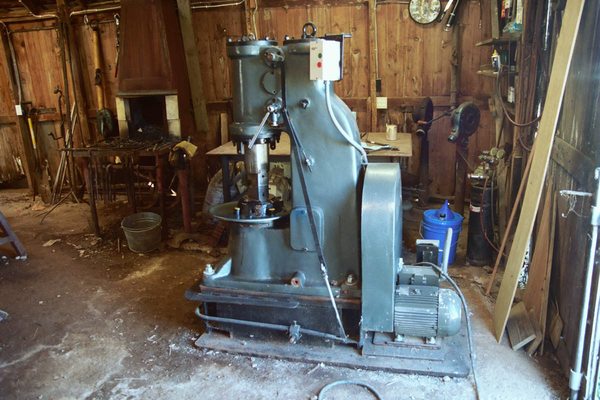
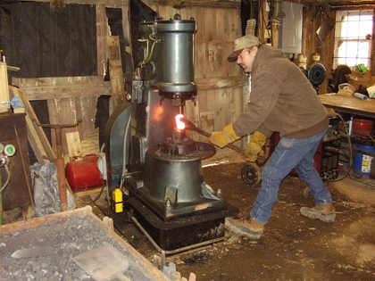
All photos in this treatise are of the author's air hammer. The author's hammer has been used for some heavy work in a very dirty environment and consequently the paint has been scorched and chipped. All exposed parts of the hammer routinely become covered with a gritty mud made up of oil and dust and crushed iron scale. Frequent cleaning leads to more scouring of the paint job as the oil and grit are wiped away. This is a real hammer that is used for real work so visitors should not expect to see a new hammer with a beautiful new paint job. This is however, the place to see how well this hammer performs at maximum forging capacity in a dirty unheated shop.
Short video clips of STC-88 hammer tapering very thin rods and forging leaves. Tapering video demonstrates the excellent control this hammer has despite being much too large for the work being done. The second video shows leaves being forged in two steps, using hand held dies. The dies were made on this hammer also.
Video data: Tapering video time 0:58, and file size 3.8 MB http://www.beautifuliron.com/Vid/VinePicketts2007tapersshort.wmv . Leaf forging video time is 1:51 seconds and file size 7.2 MB http://www.beautifuliron.com/Vid/VinePicketts2007leavesnarrativ.wmv .
![]()
![]() Short
video clips of this hammer operating, click on the movie pictures at right or
click the links below. To save this video to your computer; right click choose
"Save target as". Video shows the author's hammer during shouldering and drawing,
cutting, and a maintenance test run. The author was just playing with the hammer
while making this video.
Short
video clips of this hammer operating, click on the movie pictures at right or
click the links below. To save this video to your computer; right click choose
"Save target as". Video shows the author's hammer during shouldering and drawing,
cutting, and a maintenance test run. The author was just playing with the hammer
while making this video.
Video data: http://www.beautifuliron.com/Vid/STC88_Shoulderanddraw.wmv Shouldering and drawing file size is 1.6 MB and time is 1:34. http://www.beautifuliron.com/Vid/STC88_Cutter.wmv Cutting video is .98 MB and time is 58 seconds.
![]()
![]() YouTube
Video - Making Vine Wrapped Picketts. The videos linked here (on YouTube) show
the entire project with full narration. Visitors can see that air hammer work
makes up only a small part of the job. After the forging is done, there is still
assembly and cleaning. The air hammer is an asset that makes it easier for the
smith to forge special tooling, and much of the heavier production forging. This
video is 12 minutes long and was broken into two parts, thus the reason for
displaying two link icons at right.
YouTube
Video - Making Vine Wrapped Picketts. The videos linked here (on YouTube) show
the entire project with full narration. Visitors can see that air hammer work
makes up only a small part of the job. After the forging is done, there is still
assembly and cleaning. The air hammer is an asset that makes it easier for the
smith to forge special tooling, and much of the heavier production forging. This
video is 12 minutes long and was broken into two parts, thus the reason for
displaying two link icons at right.
The purpose for the workstand is to raise the hammer to a more convenient height for forging. The STC-88 looks like a miniature Chambersburg forging hammer. All dimensions are literally scaled down in size and the working surface of the lower die is approximately 21 inches above the floor - much too low for most blacksmiths to work with. With careful planning and design, the workstand will raise the height of the lower die to a more convenient and efficient working height while at the same time provide a stable, rugged, and safe mounting surface or platform for the hammer frame.
NOTE: when describing the "left" or "right" sides of a machine, I refer to the machine's right or left, not the user's right or left. In other words the right side of a machine is on the users left when the user is facing the front of the machine. Example; the hammer photo at top of this page shows the machine left side.
 Materials. This list of materials will build a
hammer work stand for the Striker/Shanxi STC-88 with the lower die positioned
approximately 34-1/2" above the workroom floor. Steel floor plate 1" x 31" x 60".
Machine deck plate 1" x 21" x 38". Box sides and gussets 3/4" x 10" x ?. Wood
cushioning boards 2 each - 5/4" Oak 12" x 38". Hammer mounting bolts 4 each - 1" x
7" plus washers and locknuts.
Materials. This list of materials will build a
hammer work stand for the Striker/Shanxi STC-88 with the lower die positioned
approximately 34-1/2" above the workroom floor. Steel floor plate 1" x 31" x 60".
Machine deck plate 1" x 21" x 38". Box sides and gussets 3/4" x 10" x ?. Wood
cushioning boards 2 each - 5/4" Oak 12" x 38". Hammer mounting bolts 4 each - 1" x
7" plus washers and locknuts.
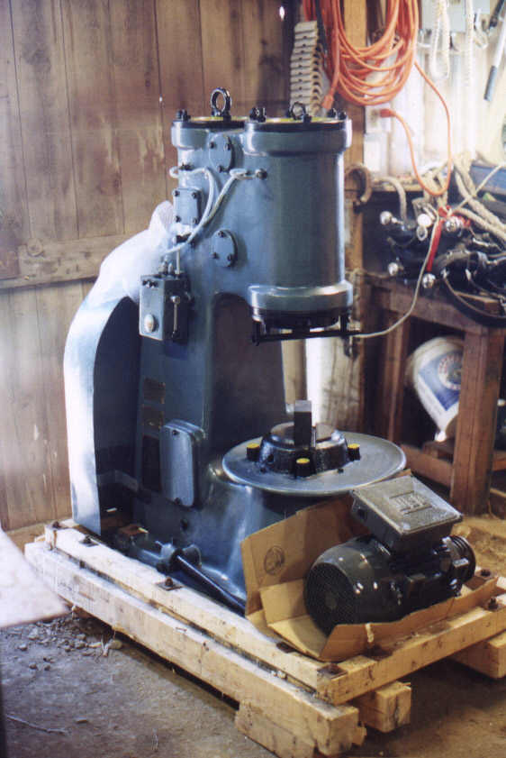
Unpacking the shipping crate. The hammer is very heavy and must be moved with a forklift. I pushed the hammer as far into the shop as possible while still allowing space to build the workstand. A lot of equipment ships with the hammer and everything must be unpacked and inventoried. The owner's manual includes plans for a concrete base, and many of the items shipped with the hammer are for use with a concrete base. As the project begins, the shop is in total disarray.
NOTE: For safety, the hammer remained bolted to the shipping pallet until ready to place on newly built workstand.
Getting started - initial planning and project development. I decided to make a steel workstand for my hammer. Accurate dimensions were needed before layout and cutting could begin. The shipping crate was disassembled and all small items that had been packed in the crate were moved away from the hammer - to allow the base of the machine to be measured. To aid in planning the construction of the workstand base, I made a set of crude drawings to help plan the work. These drawings are shown in the next paragraph below. Measurements were taken to determine all "known" dimensions of the lower hammer die height (from bottom of hammer frame to forging surface of lower die), thickness of the steel floor plate & thickness of the upper deck plate, and thickness of the wooden cushion planks. These measurements were added to the drawings.

 Determining
height of the box frame sides of the workstand. The easiest way to begin this
work, is to first decide upon an ideal height of the bottom hammer die. This ideal
die height for the lower die, was the key dimension that will be used to determine
the total heights of the steel box sides of the workstand. I decided to set the
anvil die height at 34-1/2" (89.7cm) above the floor. Next, by plugging in known
dimensions of the lower hammer die height (measuring the physical height of the
lower die to the bottom floor surface of the hammer frame), thickness of floor
plate, thickness of deck plate, thickness of wooden hammer pad, I was then able to
find the unknown height of the steel box sides for the hammer base. Here are the
known dimensions that I started with - the anvil die was 21-1/2" (56cm) above the
bottom of the cast machine base, the floor plate was 1" (26mm) thickness, the deck
plate was 1" thickness, and the wooden pad between hammer and deck plate was also
1" thick. The total combined dimensions added up to 24-1/2" inches (21-1/2" +
1" + 1" + 1" = 24-1/2"). By subtracting these known dimensions from the
desired hammer die height, I determined that the steel box sides of the workstand
needed to be 10" inches tall.
(34 1/2" - 24
1/2") = 10".
Determining
height of the box frame sides of the workstand. The easiest way to begin this
work, is to first decide upon an ideal height of the bottom hammer die. This ideal
die height for the lower die, was the key dimension that will be used to determine
the total heights of the steel box sides of the workstand. I decided to set the
anvil die height at 34-1/2" (89.7cm) above the floor. Next, by plugging in known
dimensions of the lower hammer die height (measuring the physical height of the
lower die to the bottom floor surface of the hammer frame), thickness of floor
plate, thickness of deck plate, thickness of wooden hammer pad, I was then able to
find the unknown height of the steel box sides for the hammer base. Here are the
known dimensions that I started with - the anvil die was 21-1/2" (56cm) above the
bottom of the cast machine base, the floor plate was 1" (26mm) thickness, the deck
plate was 1" thickness, and the wooden pad between hammer and deck plate was also
1" thick. The total combined dimensions added up to 24-1/2" inches (21-1/2" +
1" + 1" + 1" = 24-1/2"). By subtracting these known dimensions from the
desired hammer die height, I determined that the steel box sides of the workstand
needed to be 10" inches tall.
(34 1/2" - 24
1/2") = 10".
NOTE: 1" (one inch) in the U.S. measurement equals approximately 26 mm.
MEASURE EVERYTHING! Never ever assume that all mounting bolt positions are identical on both sides of machine. The spacing of the hammer mounting bolt holes on the left side of my air hammer are different from the bolt hole spacing on the right side. This anomaly in bolt positions in large castings is very common and I strongly recommend everyone check hole spacing prior to marking and drilling the hammer mounting holes.
Bolt hole positions could be off by an inch or more from one side to the other. Measure for square. Bolt hole positions on one side could be offset and out of square from one side to the other. Measure every detail and measure for square positioning on one side compared with the opposit side of the machine.
 Measuring
for length of the floor plate. The motor was placed behind the hammer with
belt pulleys aligned, and the total combined length from front of the hammer base
to the rear of the motor was measured. This last measurement was needed to
determine part of the overall length of the floor plate. Every dimension was
double checked and triple checked.
Measuring
for length of the floor plate. The motor was placed behind the hammer with
belt pulleys aligned, and the total combined length from front of the hammer base
to the rear of the motor was measured. This last measurement was needed to
determine part of the overall length of the floor plate. Every dimension was
double checked and triple checked.
NOTE: that the floor plate will be 2 inches longer than the total combined length of the hammer and motor, and the floor plate extends past the rear of the motor to prevent the motor from colliding with walls or other objects when the hammer is moved.
Planning and layout for the box frame. The simplest and quickest way to begin the layout and fabrication of the box frame, is to first cut the upper deck plate (hammer mounting surface) and then accurately transfer mounting bolt positions from the hammer frame to the deck plate.
 Deck
plate (hammer mounting surface) was cut first. No other parts of the box frame
were cut until after all layout work was completed on the deck plate. The hammer
base was carefully measured and all dimensions were recorded on paper. The
finished deck plate was made slightly larger than the base - 1/2" longer and 1/2"
wider, than the base of the hammer. The deck plate extends 1/4" past each side of
the hammer base, and the plate extends 3/8" past the front of the hammer base.
This lends support under the wooden pad that will be placed between the hammer and
workstand.
Deck
plate (hammer mounting surface) was cut first. No other parts of the box frame
were cut until after all layout work was completed on the deck plate. The hammer
base was carefully measured and all dimensions were recorded on paper. The
finished deck plate was made slightly larger than the base - 1/2" longer and 1/2"
wider, than the base of the hammer. The deck plate extends 1/4" past each side of
the hammer base, and the plate extends 3/8" past the front of the hammer base.
This lends support under the wooden pad that will be placed between the hammer and
workstand.
NOTE: the flywheel is fitted very close to the hammer, so the deck plate should be positioned flush with the hammer base or extend no more than 1/8" past the rear. Keep it tight in back.
Positions of bolt holes (at the base of the hammer) were transferred to the deck plate and double checked for accuracy. This was the time to catch mistakes before the work went any farther. On my hammer, I found one of the cast mounting bolt holes to be slightly out of square with the machine. This oddity was carefully transferred to the layout drawings on the deck plate. The deck plate was marked "this side up" to prevent mistakes, and 1-1/8" bolt holes were then drilled.
NOTE: bolt holes in a cast frame should never be considered perfectly spaced and should always be carefully measured to accurately determine the exact positions before cutting and drilling the workstand. Measure and measure again.
After drilling, the deck plate was used as an aid to help plan the layout and dimensions and construction of the box frame. A 1-inch mounting bolt was inserted in each of the holes in the deck plate, and after placing a large wrench on the bolt heads, the positions of the wrench and the intended box frame dimension lines were visually inspected to see if there was enough clearance to allow a wrench to fit inside the planned bolt access wells. Drawings on the deck plate were adjusted as needed to make everything fit before cutting the remaining steel parts.
Cutting the remaining steel parts of the workstand. The 1" floor plate was made 31" x 60" long. The floor plate would extend 1/2" in front of the box frame, and to the rear the floor plate extended roughly 2 inches past the rear of the motor. The length of the floor plate was determined when I took my first measurements of the hammer (see the entry above titled "Measuring for the length of the floor plate"). The long extension at the rear of the hammer workstand would prevent the motor from striking walls and other objects when the hammer is moved. All corners on the box frame, deck plate, and floor plate, were chamfered or rounded off to remove sharp corners.


 Welding
the box frame. The box sides were cut from 3/4" x 10" flat steel and welded
together. Concentrating on building the box first
without the forklift
channel irons. The forklift slots were made from 2" x 6" channel (inside
dimensions are of coarse smaller than this so forklift forks of about 5" x 1-1/2"
will fit in these slots). After the box frame was welded together, I cut the fork
channels to length and then cut the slots in the corners of the box frame to
accept the fork lift channels. These are not welded together until the next step.
Welding
the box frame. The box sides were cut from 3/4" x 10" flat steel and welded
together. Concentrating on building the box first
without the forklift
channel irons. The forklift slots were made from 2" x 6" channel (inside
dimensions are of coarse smaller than this so forklift forks of about 5" x 1-1/2"
will fit in these slots). After the box frame was welded together, I cut the fork
channels to length and then cut the slots in the corners of the box frame to
accept the fork lift channels. These are not welded together until the next step.
NOTE: the spacing of front and rear hammer mounting bolt holes are not identical, and the size and position of the front and rear bolt wells are also different. Up to this point in the construction it wasn't necessary to keep the box facing one direction, BUT now it was important to orientate the box correctly - BEFORE welding the box frame to the floor plate.
Welding box frame to the floor plate. The front of the box was placed 1/2" behind the front edge of the floor plate and centered side to side on the floor plate. The forklift channels were placed inside the box frame with the open sides of the channel facing down against the floor plate. The frame was tack-welded to the floor plate, the fork channels were slipped into place and tack welded, and then everything was welded to the floor plate using full length beads and welded on both sides.
 Reinforcing
gussets support the middle of the forklift channels and prevent the fork
channels breaking away from the floor plate if the force exerted by the forklift
becomes too great. To create the gusset shapes, a cardboard pattern was made to
fit closely around the fork lift channels. The gussets extend 3-1/2" beyond both
sides of each fork channel. The gussets were then cut and welded in place.
Reinforcing
gussets support the middle of the forklift channels and prevent the fork
channels breaking away from the floor plate if the force exerted by the forklift
becomes too great. To create the gusset shapes, a cardboard pattern was made to
fit closely around the fork lift channels. The gussets extend 3-1/2" beyond both
sides of each fork channel. The gussets were then cut and welded in place.
The box was filled with sand and the deck plate was then placed on the box and a quick check was made to insure that the front and rear hammer mounting holes were in the correct position. The upper deck plate was then welded in place.
NOTE: in the photos (at right), the large hole in the deck plate is for filling the box frame with sand. The sand fill hole will be under the rear frame of the hammer - not under the anvil block!

 The
wooden cushion between the hammer and workstand was made from 5/4" (30 mm)
thickness oak boards. The oak boards were placed on top of the newly welded deck
plate and size dimensions and bolt hole positions were scribed onto the boards.
The boards were cut to size and drilled for hammer mounting bolts.
The
wooden cushion between the hammer and workstand was made from 5/4" (30 mm)
thickness oak boards. The oak boards were placed on top of the newly welded deck
plate and size dimensions and bolt hole positions were scribed onto the boards.
The boards were cut to size and drilled for hammer mounting bolts.
The workstand was moved to its final position in the shop, the oak cushion boards set on top of the deck plate, and the hammer was lifted onto the workstand using the lifting eye provided for the rear cylinder. The hammer was aligned to proper position by levering it around with a tapered bar placed through the mounting bolt holes, and the hammer was bolted down. The hammer was now ready for build-up.
 Motor
mounting plate. The large motor mount is made from several pieces of 3/4"
steel plate. To facilitate the tightening of drive belts the motor mount plate is
tipped sloped to one side of the machine as seen in the pictures. On my hammer
base I chose to move the plate to one side of the hammer so that it extends about
2 inches past the side of the box frame. This proved to be a small cosmetic
mistake. The offset motor mounting base placement caused the motor to need more
lateral adjustment to the left to tighten the belts and consequently I needed to
trim the flywheel cover to allow the motor to move farther to the side. I
recommend following the distributor's design and centering the sloped motor mount
below the flywheel rather than offsetting it like I did. However, despite the
cosmetic flaw of being built offset, this sloped motor tensioning system works
very well.
Motor
mounting plate. The large motor mount is made from several pieces of 3/4"
steel plate. To facilitate the tightening of drive belts the motor mount plate is
tipped sloped to one side of the machine as seen in the pictures. On my hammer
base I chose to move the plate to one side of the hammer so that it extends about
2 inches past the side of the box frame. This proved to be a small cosmetic
mistake. The offset motor mounting base placement caused the motor to need more
lateral adjustment to the left to tighten the belts and consequently I needed to
trim the flywheel cover to allow the motor to move farther to the side. I
recommend following the distributor's design and centering the sloped motor mount
below the flywheel rather than offsetting it like I did. However, despite the
cosmetic flaw of being built offset, this sloped motor tensioning system works
very well.
How it works - tightening the belts. The first thing the reader will notice in the photo, is that the motor mounting base is built on a sloped or tilted surface. The motor and belt pulley are mounted directly below the hammer flywheel. The sloped surface of the motor mounting base causes the motor to move closer too, or farther away from, the flywheel, depending on which way the motor is moved on the mounting base. Motor tension adjustment screws help apply more force to move the motor up or down on the sloped mounting base. Slots have been cut into the mounting base to allow the motor and tensioning plate to slide up or down on the mounting base. The entire mounting structure has been welded solidly to the hammer frame base.
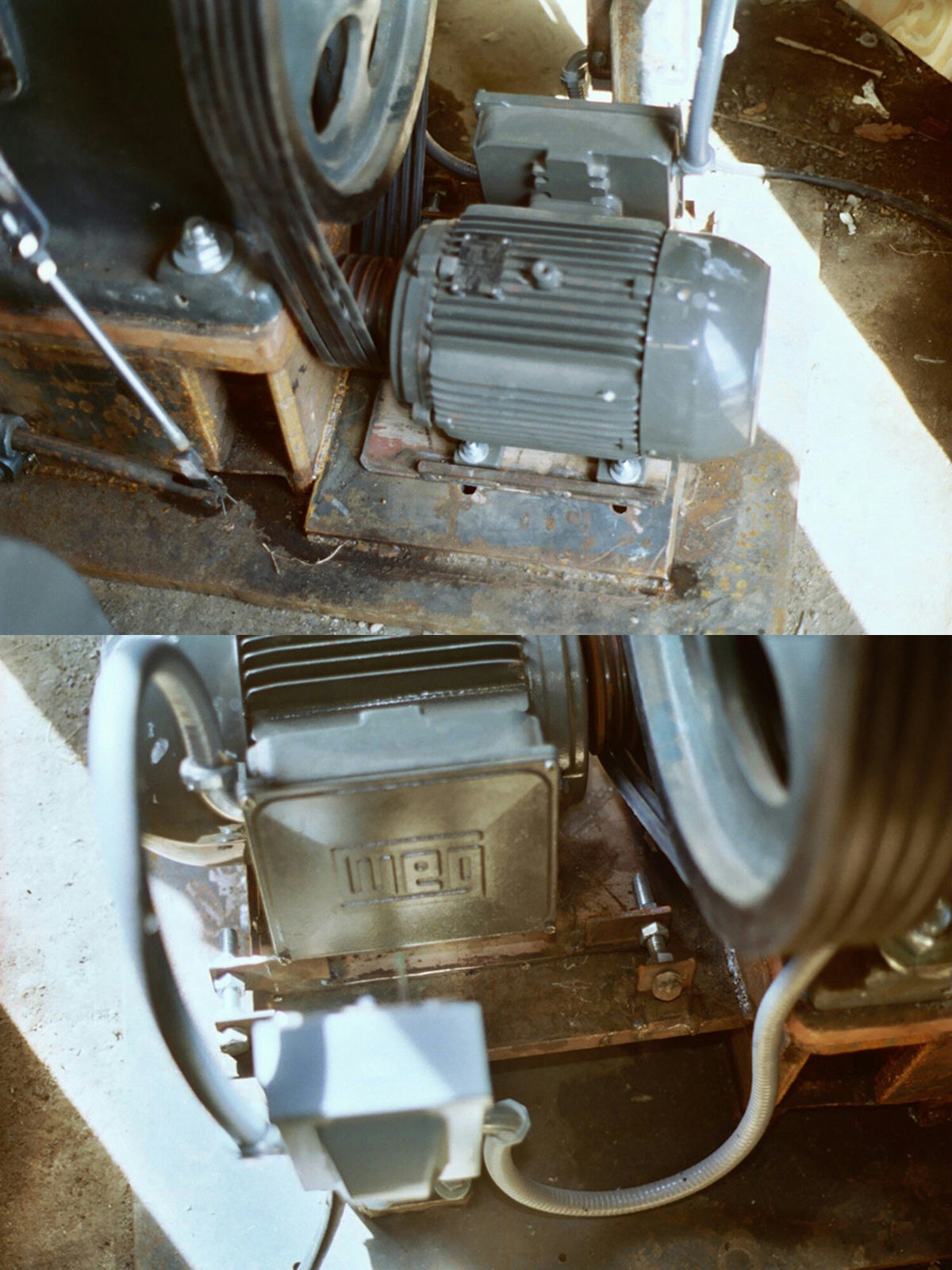 Motor
tensioner. The motor is connected to the flywheel with 5 v-belts. The motor
must be pushed against the drive belts with enough force to remove all slack in
the belts and prevent slippage. This called for a sliding tensioner plate between
the motor and motor mounting base, and threaded rods and nuts to force the
tensioner and motor against the belts. The tensioner plate is a separate plate
installed between the motor and the base of the hammer frame. The motor can be
moved forcefully against the drive belts by rotating the nuts on the tension
screws (threaded rods). The tension screws are installed through tabs that have
been welded to the hammer frame. The tension screws and nuts press against the
ears on the edge of the tensioner plate - thus forcing the tensioner plate to move
sideways - tightening the motor pulley against the drive belts.
Motor
tensioner. The motor is connected to the flywheel with 5 v-belts. The motor
must be pushed against the drive belts with enough force to remove all slack in
the belts and prevent slippage. This called for a sliding tensioner plate between
the motor and motor mounting base, and threaded rods and nuts to force the
tensioner and motor against the belts. The tensioner plate is a separate plate
installed between the motor and the base of the hammer frame. The motor can be
moved forcefully against the drive belts by rotating the nuts on the tension
screws (threaded rods). The tension screws are installed through tabs that have
been welded to the hammer frame. The tension screws and nuts press against the
ears on the edge of the tensioner plate - thus forcing the tensioner plate to move
sideways - tightening the motor pulley against the drive belts.

 MODIFICATION
- Treadle pivot bolts relocated to workstand. These are the original
treadle pivot bolts that were installed in the hammer frame by the manufacturer. I
welded the bolts to the workstand at a location that is directly below the
original pivot positions on the hammer frame. The height of the treadle bolts
(above floor level) is roughly the same as original pivot holes on the hammer
frame - approximately 3 inches (75 mm).
MODIFICATION
- Treadle pivot bolts relocated to workstand. These are the original
treadle pivot bolts that were installed in the hammer frame by the manufacturer. I
welded the bolts to the workstand at a location that is directly below the
original pivot positions on the hammer frame. The height of the treadle bolts
(above floor level) is roughly the same as original pivot holes on the hammer
frame - approximately 3 inches (75 mm).
Adjustable treadle throttle link. The original throttle link must be lengthened after relocating the treadle pivot bolts. But what length would work best? And if I made changes later to the position of the treadle, the changes would again effect the length of the throttle link. An adjustable treadle throttle link allows flexibility in adjustment of the treadle to any desired height.
MODIFICATION - Making the adjustable throttle link. I cut the treadle throttle link at approximately 3-1/2 inches (93 mm) from the lower connection (near the treadle), and welded a 5/8" (approx.15 mm) threaded rod to the short section of throttle link. The long upper section of the throttle link was punched and drifted and bent 90 degrees to accept the 5/8" threaded rod. The threaded rod was then inserted through the drifted hole and reinstalled on the machine and, after establishing the desired length between the threaded rod and nuts, the link was adjusted for best effect.

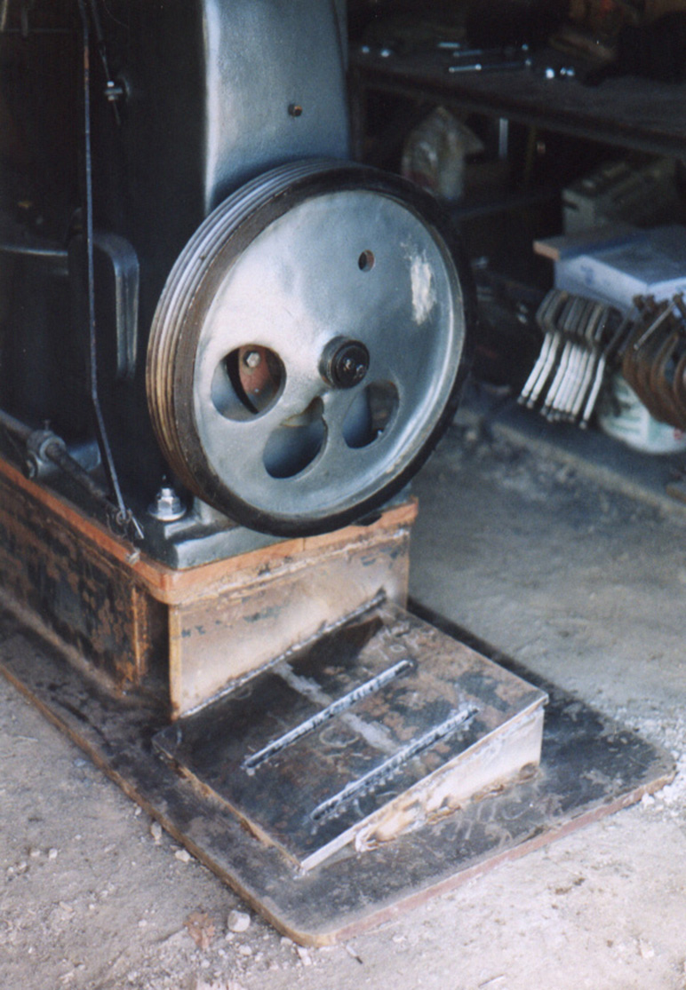
 Treadle
guard. The purpose of the treadle guard is to prevent the treadle from being
depressed if any part of the work should happen to fall off the hammer during
forging. This includes tooling and other objects that are laying on the scale pan
that might fall off the pan and strike the treadle while the hammer is running.
Treadle
guard. The purpose of the treadle guard is to prevent the treadle from being
depressed if any part of the work should happen to fall off the hammer during
forging. This includes tooling and other objects that are laying on the scale pan
that might fall off the pan and strike the treadle while the hammer is running.
The treadle guard seen here is made of 1/4" x 3-1/2" (6 mm x 93 mm) flat steel, welded all around the top of the workstand. The large gap between the treadle and guard allows me to place the large steel toes of my work boots between the guard and treadle from every possible angle. The treadle guard on my hammer is cut with a slight taper towards the rear end of the guard - matching the shape or outline of the treadle.
 Overview
of motor and electrical installation. The electrical installation shown here
is very different from the original Striker Tool Company electrical installation
plan. I had three concerns about how the electrical installation should be
performed on my equipment. #1.) The rear of my hammer is near the large entrance
doors at the front of my shop, the doors are poorly sealed and allow rain and snow
to fall on the rear of the hammer and motor. To prevent problems caused by
exposure to rain and snow, I wanted all wire electrical wiring to be run through
weather proof panels and conduit. #2.) I wanted the power cable to enter and
terminate in a safety disconnect box on the back of the hammer, thus limiting
damage to the cable and disconnect box connections in the event that personnel or
machinery trip over or snag the power cable and pulling it out of the disconnect
box. #3.) I wanted the starter to be mounted on the machine - not beside it. And I
wanted simple conduit protected wire runs from starter to the disconnect box and
to the motor.
Overview
of motor and electrical installation. The electrical installation shown here
is very different from the original Striker Tool Company electrical installation
plan. I had three concerns about how the electrical installation should be
performed on my equipment. #1.) The rear of my hammer is near the large entrance
doors at the front of my shop, the doors are poorly sealed and allow rain and snow
to fall on the rear of the hammer and motor. To prevent problems caused by
exposure to rain and snow, I wanted all wire electrical wiring to be run through
weather proof panels and conduit. #2.) I wanted the power cable to enter and
terminate in a safety disconnect box on the back of the hammer, thus limiting
damage to the cable and disconnect box connections in the event that personnel or
machinery trip over or snag the power cable and pulling it out of the disconnect
box. #3.) I wanted the starter to be mounted on the machine - not beside it. And I
wanted simple conduit protected wire runs from starter to the disconnect box and
to the motor.
Electrical safety disconnect box at rear of workstand. The safety disconnect box is located on the rear of the steel workstand floor plate - next to the motor. The mounting bracket is a simple affair made of 1/4-inch x 2-inch (6 mm x 50 mm) angle iron with a 1/4-inch x 4-inch (6 mm x 100 mm) square plate welded to the bottom end of the angle iron, and another similar size plate welded to the upper end of the angle iron for mounting the safety disconnect box. The plates are of coarse drilled for bolting the disconnect box and bolting to the floor plate. A piece of 1-inch x 4-inch (26 mm x 100 mm) square plate was drilled and tapped for 1/2-inch (13 mm) bolts, and welded to the floor plate, next to the motor. In this way I could assemble the disconnect box with the mounting bracket and then quickly bolt everything down to the floor plate of the workstand.


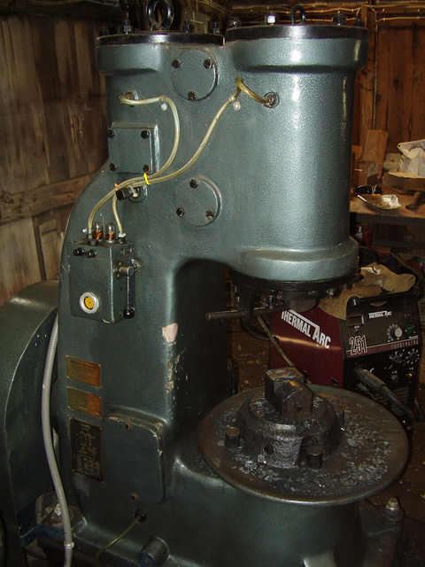
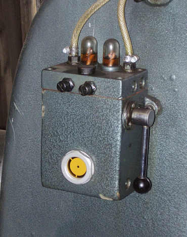
 Swiveling
bracket on side of hammer supports the starter box. The Striker™ hammer was
provided with a separate stand for mounting the motor starter but, I chose to
install the starter on the side of the hammer. A two-piece forged bracket was
bolted to the top of the rear cylinder head using the lifting eye and one of the
cylinder head bolts. The head bracket was forged with an offset approximately 1/4
inch (6 mm) to allow it to lay flat across both the center and sides of the
cylinder head. The two-piece bracket is assembled with a single bolt to allow the
starter mount to be swiveled into desired position before tightening the bracket
together. The starter box was bolted to the bracket. This setup places the starter
box in a location that this author found to be most ideal for operating the
hammer. This location for the starter box keeps the box away from the forging work
and away from traffic in the shop, and yet the starter box is within easy reach of
the hammer operator.
Swiveling
bracket on side of hammer supports the starter box. The Striker™ hammer was
provided with a separate stand for mounting the motor starter but, I chose to
install the starter on the side of the hammer. A two-piece forged bracket was
bolted to the top of the rear cylinder head using the lifting eye and one of the
cylinder head bolts. The head bracket was forged with an offset approximately 1/4
inch (6 mm) to allow it to lay flat across both the center and sides of the
cylinder head. The two-piece bracket is assembled with a single bolt to allow the
starter mount to be swiveled into desired position before tightening the bracket
together. The starter box was bolted to the bracket. This setup places the starter
box in a location that this author found to be most ideal for operating the
hammer. This location for the starter box keeps the box away from the forging work
and away from traffic in the shop, and yet the starter box is within easy reach of
the hammer operator.
The Sprecher-Schuh Kwikstarter magnetic motor starter shown on this page is used for single-phase and 3-phase applications. Note that the starter shown here has been rigged for single-phase use. This is a complete self-contained motor starter consisting of a motor start contactor relay and an overload relay. The entire unit comes pre-installed in a small enclosed polycarbonate panel/box. Sprecher-Schuh website is here: http://www.ssusa.cc/ . Sprecher-Schuh has posted a library with documentation on all their products including wiring diagrams and technical drawings.
NOTE: this is a single-phase 220volt installation in my shop.


 Overview
of wiring runs. The power cable enters the bottom of the disconnect box. Click
on the thumbnails of the disconnect box (two photos near right). There are three
wires in the cable, black and green are hot 220-volt wires. The beige color wire
is a neutral and I connected it to the common ground lugs at the left side of the
box. This neutral line is also grounded in the main power service panel that
enters the shop. The hammer electrical circuit is grounded for safety.
Overview
of wiring runs. The power cable enters the bottom of the disconnect box. Click
on the thumbnails of the disconnect box (two photos near right). There are three
wires in the cable, black and green are hot 220-volt wires. The beige color wire
is a neutral and I connected it to the common ground lugs at the left side of the
box. This neutral line is also grounded in the main power service panel that
enters the shop. The hammer electrical circuit is grounded for safety.
Red and blue hot wires from bottom of disconnect breaker, are routed through conduit to the 'L' terminals of the motor starter. Green and black wires from the 'T' series terminals (at bottom of motor starter/overload breaker) are routed back through disconnect box and through conduit to motor. White neutral wires are connected from the common ground lugs in the disconnect box, to the ground lug in the motor, and to the neutral lug inside of the motor start relay box.
NOTE: the neutral lug inside the motor starter box is a dead end. I included this wire for future modifications that would use the starter wiring.

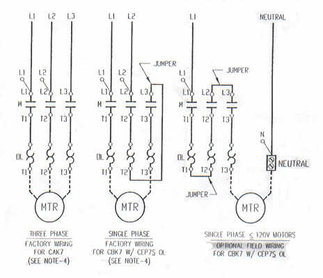 The
motor circuit. Under construction. The wiring diagram (wiring diagram at near
right) shows three configurations for 3 different voltages and phases. Note that
the diagram does not show the fourth (spare) set of contacts that are
available on the motor starter relay. I have modified the 240v single-phase
diagram (wiring diagram at second right) to show the NO contacts. The NO contacts
are not part of motor run circuit. NO means 'Normally Open.' All of
the contacts are in fact normally open, but only the 'L' series and 'T' series
connections are part of the motor circuit. The NO contacts are spares available
for other optional use. There are 4 sets of contacts on the starter relay (L1, L2,
L3, & spare NO), and there are 3 circuits in the overload device(T1, T2, T3). The
240v single-phase diagram shows a jumper wire between T2 & L3. I had to move this
jumper to connect from T2 on the bottom of the overload device to L3 at the top of
the relay.
The
motor circuit. Under construction. The wiring diagram (wiring diagram at near
right) shows three configurations for 3 different voltages and phases. Note that
the diagram does not show the fourth (spare) set of contacts that are
available on the motor starter relay. I have modified the 240v single-phase
diagram (wiring diagram at second right) to show the NO contacts. The NO contacts
are not part of motor run circuit. NO means 'Normally Open.' All of
the contacts are in fact normally open, but only the 'L' series and 'T' series
connections are part of the motor circuit. The NO contacts are spares available
for other optional use. There are 4 sets of contacts on the starter relay (L1, L2,
L3, & spare NO), and there are 3 circuits in the overload device(T1, T2, T3). The
240v single-phase diagram shows a jumper wire between T2 & L3. I had to move this
jumper to connect from T2 on the bottom of the overload device to L3 at the top of
the relay.
Magnetic motor starter - theory of operation. The theory presented here describes only the operation of the Sprecher-Schuh Kwikstarter described above. With the push of a button, the motor starter connects the motor to an electrical source through contactors and maintains that connection by the use of electro-magnetic attraction until electrical power is lost or until the starter senses a jam or over-current condition, at which time the electro-magnetic circuit is broken and the contacts separate - thus opening the motor electrical source connection. Motor start relays allow fast switching of high current circuits without excessive burning of switching contacts. Modern motor starters are often provided with built-in or add-on overload protection devices.
NOT DONE
Grease requirements, specifications. Use the best grease available. I recommend using the best molybdenum marine duty grease.

Bearing Lubrication - 3 Grease Zerk Locations. A lubrication reference placard is attached to the lower right side of hammer frame. The lubrication placard shows the locations and lubrication frequencies of bearings that require periodic lubrication (greasing).
Warning! Electrical power must be locked out before removing guards and opening access panels!
Guards and access panels must be removed to lubricate the STC-88 hammer. Some new hammer owners might be a little uncomfortable disassembling their machine and damaging the beautiful paint job. Removing guards and access panels is part of routine maintenance. Lubrication is a requirement! Two grease points are located inside the hammer frame and both access doors must be removed to gain entry for lubricating these internal grease zerks. A third grease point is located behind the flywheel, so the flywheel guard must be removed to access this grease point.
NOTE. Paint and seals will be damaged during typical maintenance activities. The silicone sealant is cheap to replace, and new paint can be applied over scratches.
Warning! Flywheel and crankshaft could move unexpectedly and cause serious injury!

 Rear
crankshaft bearing grease port is located between the flywheel and hammer
frame. (See the photos at right) The flywheel guard must be removed to gain access
to the flywheel. Rotate the flywheel so that one of the lightening holes is
located directly on top at the 12:00 o'clock position. The grease port can be seen
through the flywheel lightening hole when the lightening hole is rotated straight
up. The grease port is sealed with a check ball/check valve. Use a needle-tip
attachment with the grease gun to force grease into this port. The grease port is
very small so it may be necessary to first clean the back of the machine to find
it. Wipe grease port clean after greasing.
Rear
crankshaft bearing grease port is located between the flywheel and hammer
frame. (See the photos at right) The flywheel guard must be removed to gain access
to the flywheel. Rotate the flywheel so that one of the lightening holes is
located directly on top at the 12:00 o'clock position. The grease port can be seen
through the flywheel lightening hole when the lightening hole is rotated straight
up. The grease port is sealed with a check ball/check valve. Use a needle-tip
attachment with the grease gun to force grease into this port. The grease port is
very small so it may be necessary to first clean the back of the machine to find
it. Wipe grease port clean after greasing.
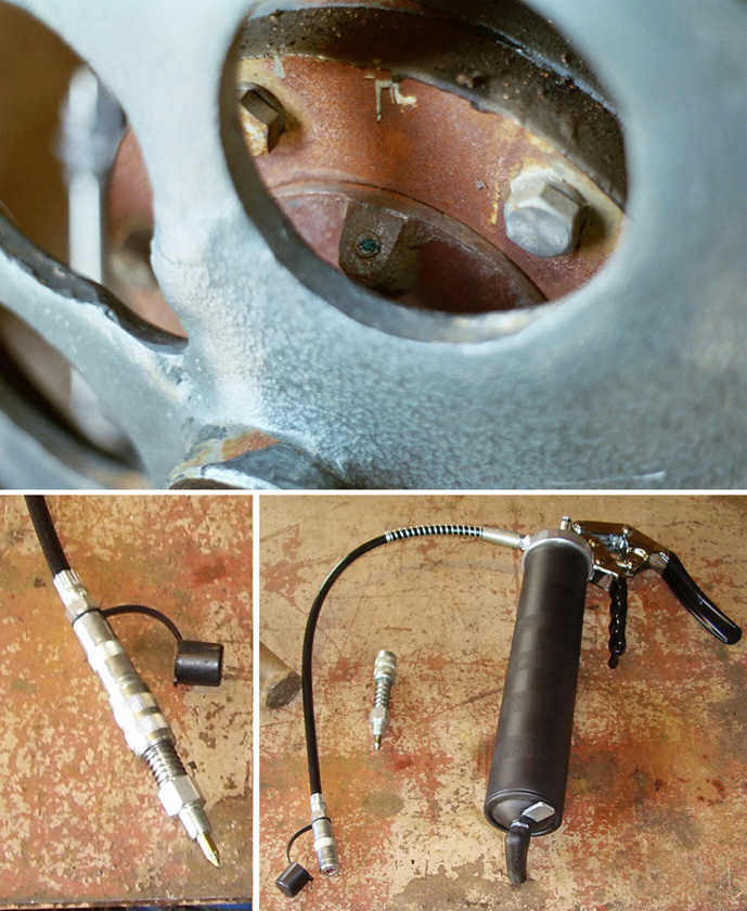
HINT - Needle point grease gun tip. In the photo (at near right) a needle point grease gun tip is shown. The needle point tip is made of steel and/or brass. A rubber needle grease grease tip will not work well. The grease tip must push through a check ball and seal itself to the inner opening of the grease port. Steel and brass needle point grease tips are best suited for this task. This author recommends using a steel or brass needle point greasing tip similar to the grease tip shown in the photos at right. The needle point tip has a grease zerk on its end to allow it to be connected temporarily to the grease gun hose. After the task is completed, the tip can be quickly and easily removed.

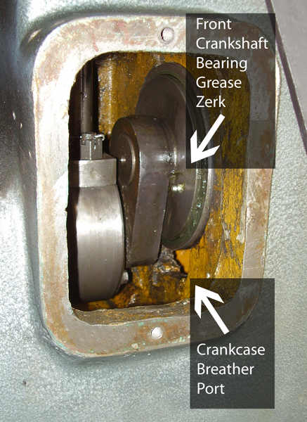 Front
crankshaft bearing grease zerk is accessed by removing the left-side access
panel. The access panel is held in place with two bolts. The silicone sealant
sticks to the hammer frame, so it may be necessary to carefully pry the access
panel off. Rotate the flywheel so that the pitman bearing (lower end of
connecting-rod) is at its lowest position - see photo at right. This places the
front crankshaft bearing grease zerk within easy reach on the left side of the
machine. DO NOT reach around, or through, the connecting-rod and crankshaft
because the crankshaft could still move unexpectedly and cause serious injury.
Using a grease gun with a flexible hose, reach inside the frame and connect the
grease gun tip to the zerk and apply grease. Clean excess grease off crankshaft
and clean up old grease from inside walls of hammer frame, and inside surface of
access panel.
Front
crankshaft bearing grease zerk is accessed by removing the left-side access
panel. The access panel is held in place with two bolts. The silicone sealant
sticks to the hammer frame, so it may be necessary to carefully pry the access
panel off. Rotate the flywheel so that the pitman bearing (lower end of
connecting-rod) is at its lowest position - see photo at right. This places the
front crankshaft bearing grease zerk within easy reach on the left side of the
machine. DO NOT reach around, or through, the connecting-rod and crankshaft
because the crankshaft could still move unexpectedly and cause serious injury.
Using a grease gun with a flexible hose, reach inside the frame and connect the
grease gun tip to the zerk and apply grease. Clean excess grease off crankshaft
and clean up old grease from inside walls of hammer frame, and inside surface of
access panel.
HINT - Hand grip operated grease gun. The most convenient style of grease gun for greasing the air hammer, is the hand grip operated style. See the photos at right. This style of grease gun (as seen in the photos here) allows the maintenance worker to operate the grease gun with one hand, while at the same time, holding the grease gun hose in position with his other hand to prevent the tip from leaking or disconnecting itself from the grease zerk.

 The
connecting-rod bearing grease zerk is accessed by removing the right-side
access panel. And like the access panel described in the previous paragraph, the
access panel is held in place with two bolts. The silicone sealant sticks to the
hammer frame, so it may be necessary to carefully pry the access panel off. Rotate
the flywheel so that the connecting-rod pitman is at its lowest position - see
photo. DO NOT reach around, or through, the connecting-rod and crankshaft because
the crankshaft could still move unexpectedly and cause serious injury. Connect
grease gun tip to connecting-rod grease zerk and apply grease. Clean excess grease
off connecting-rod and clean up old grease from inside walls of hammer frame.
The
connecting-rod bearing grease zerk is accessed by removing the right-side
access panel. And like the access panel described in the previous paragraph, the
access panel is held in place with two bolts. The silicone sealant sticks to the
hammer frame, so it may be necessary to carefully pry the access panel off. Rotate
the flywheel so that the connecting-rod pitman is at its lowest position - see
photo. DO NOT reach around, or through, the connecting-rod and crankshaft because
the crankshaft could still move unexpectedly and cause serious injury. Connect
grease gun tip to connecting-rod grease zerk and apply grease. Clean excess grease
off connecting-rod and clean up old grease from inside walls of hammer frame.
Inspect inside of sump oil drain port while right side access panel is removed. Note the position of the drain hose fitting on the side of the hammer frame - the drain port is located directly below the right side access panel. Use a clean rag to wipe drain port clean. Wipe out oil sump with a clean rag and inspect rag for metal shavings or other indications of mechanical trouble.
Re-sealing and re-installing access panels. Panels are fastened with two bolts. These bolts are snugged down - NOT tightened down super tight! A soft seal will prevent leakage. If oil leaks through the access panel sealant then replace the sealant - DO NOT over-tighten cover bolts. Excessively tightened bolts could break the cover panel. Cover panels are sealed with silicone sealant. I prefer to reuse the seals if they are not too badly damaged after removal. If old sealant is too badly damaged to re-use, I remove the old sealant and thoroughly clean and degrease the panel seal area, and apply a thin coat of silicone sealant and re-install after the sealant skins.
 MODIFICATION
- Grease zerks installed in treadle pivots. The treadle pivot bolts were
welded to the side of the workstand as part of my throttle linkage modification
described earlier in the Throttle Linkage & Treadle Guard chapter. In my opinion,
an un-lubricated pivot joint is a candidate for excessive wear. I installed grease
zerks in the pivot brackets so that I could lubricate these joints. I drilled the
grease zerk holes slightly above the horizontal center of the pivot bolt holes,
tapped the holes for 1/8" pipe thread, and installed 90 degree angle zerks.
Pivot bracket lubrication frequency. The pivot brackets are greased during the
same maintenance interval as the crankshaft bearings and connecting-rod pitman
bearing.
MODIFICATION
- Grease zerks installed in treadle pivots. The treadle pivot bolts were
welded to the side of the workstand as part of my throttle linkage modification
described earlier in the Throttle Linkage & Treadle Guard chapter. In my opinion,
an un-lubricated pivot joint is a candidate for excessive wear. I installed grease
zerks in the pivot brackets so that I could lubricate these joints. I drilled the
grease zerk holes slightly above the horizontal center of the pivot bolt holes,
tapped the holes for 1/8" pipe thread, and installed 90 degree angle zerks.
Pivot bracket lubrication frequency. The pivot brackets are greased during the
same maintenance interval as the crankshaft bearings and connecting-rod pitman
bearing.

![]()

![]() Recommended oils for the STC-88 air hammer:
Recommended oils for the STC-88 air hammer:
New oil name: Chevron Rando HD ISO 220
Alternate oil names: Texaco Rando HD 220
Chevron/Texaco Rando HD 220
Original oil name:
Chevron Machine Oil AW ISO 220This oil was re-named Rando HD.
Use Chevron Rando HD ISO 220 or Texaco Rando HD ISO 220. Rando HD oils will dramatically reduce oiling misting in the shop. If you are having problems of oil misting while running an air hammer - then switch to Rando HD. ISO 220 is approximately 50wt and ISO 320 is approximately 60wt. Manufacturers test results demonstrate outstanding anti-wear and corrosion inhibition characteristics, fast water separation, and oxidation stabillity. Good anti-foam and air release properties. First picture (at middle right) links to a catalog description of Chevron Machine Oil AW from the year 2000. The name was changed to Chevron Rando HD shortly after the catalog was printed. The two product reference sheets (at far right) link to PDF files of catalog information describing this same oil after it was renamed Rando HD.
Name change. Previous name was Chevron Machine Oil AW ISO 220. This oil is Currently sold under the new name Chevron Rando HD. Alternate names include Texaco Rando HD and Chevron/Texaco Rando HD.
The drip oiler supplies oil to the hammer cylinders for the purpose of lubricating the compressor piston and upper connecting-rod, ram piston, and throttle air valves. The cylinders require a continuous (un-interrupted) supply of lubricating oil at all times while the machine is in operation.
ATTENTION: -Anyang air hammer owners. While the information presented here was originally written for Striker hammer owners, Anyang hammer owners will also find this page very useful because Anyang uses the same oiler system. These oilers work very well when the owner understands how they work and how to use them properly. Beware there are some very irresponsible individuals on internet forums that are promoting one of the most foolish and poorly conceived modifications to these oiler systems that one could ever imagine. And these guys are distributors of Anyangs! Their misguided advice involves gouging out (removing) the upper cylinder oil check valve and then chopping in an after-market tube check valve. This unnecessary modification results in reduced performance of the oiler system and will lead to premature and excessive wear on the cylinders and pistons- thus dramatically shortening hammer life. The check valves in the cylinders were added by an engineer to improve oiler performance- and they work well! Leave them there. If you're having problems with your oiler system, then read and understand the principles described below, and you will be well on your way to greater performance and longer life of your hammers. The oiler section is divided into 5 important parts. Part 1, gives a quick overview of the parts and a detailed description of how the oiler operates. Part 2 features detailed instructions on priming, setting and adjusting oil flow, re-establishing oil flow after low oil condition, and adding oil and recommended oil weights. Part 3 describes in detail- each and every part of the oiler, and explains how each part works. This includes photos and diagrams of internal parts of the oiler. Part 4 gives a detailed summary of the entire path that the oil takes on its journey from the oil reservoir to the hammer cylinders. Part 5 will offer tips on disassembly and maintenance. Armed with the knowledge presented here, new hammer owners will be able to prime, set, and adjust their oilers in 2 minutes. And they will be able to troubleshoot and solve any problems they might encounter with the oiler system, in just minutes. The hammer page and oiler section are still under construction and they have a long way to go before they can ever be considered finished. Any part that appears unfinished, probably is. So you can expect more changes and additions to come later. The oiler section was written in an older era or style. It focuses on giving the reader a very detailed theory of operation, with the idea being that the hammer owner would have enough mechanical experience or training to be able to put this knowledge to use in troubleshooting or maintaining their hammer. It was written for people that can do things for themselves. If you are one of these people, then you will like this website.
#1. Drip Oiler - Overview & Theory of Operation
 Drip
oilers used on small hammers such as the Striker STC-88 forging hammer (photo
at right) consist of a reservoir with distribution and metering manifold, priming
pump, check valves/one-way valves, and hammer cylinder oil supply tubes. Metering
valves control the volume or rate of oil flow during hammer operation and the
valves are fully adjustable by hand. Drip domes on top of the reservoir manifold
allow the blacksmith to monitor oil flow. An oil level sight glass (small window)
on the front of the oiler reservoir will show a bubble when the oil level is low.
The entire oiler system is externally mounted on the right side of the hammer.
Drip
oilers used on small hammers such as the Striker STC-88 forging hammer (photo
at right) consist of a reservoir with distribution and metering manifold, priming
pump, check valves/one-way valves, and hammer cylinder oil supply tubes. Metering
valves control the volume or rate of oil flow during hammer operation and the
valves are fully adjustable by hand. Drip domes on top of the reservoir manifold
allow the blacksmith to monitor oil flow. An oil level sight glass (small window)
on the front of the oiler reservoir will show a bubble when the oil level is low.
The entire oiler system is externally mounted on the right side of the hammer.
Oil system priming required before hammer start. Priming should be done at the beginning of each day before starting the hammer and anytime that the hammer has been idle for more than a couple hours. It is normal for oil in the supply tubes to slowly drain back into the reservoir when the hammer is not operating. The priming pump is used to purge air from the oil lines and to force oil to flow through oil tubing to begin initial lubrication of the cylinders. Transparent plastic oiler tubes allow the blacksmith to observe the oil and/or air in the tubing. Owners of hammers with metal oil supply tubes cannot see the oil and/or air in the tubing and should assume that the tubing has completely drained of oil if the hammer has been idled for roughly 8 or more hours.
 Drip
oiler system uses no external power. The drip oiler works by pressure
differential alone - external mechanical or electrical power is not used.
Atmospheric pressure (ambient air) supplies the force necessary to push oil
through the oiler system. The breather/fill plug allows ambient air to flow freely
into the reservoir tank and maintains atmospheric pressure on the oil inside the
reservoir at all times. When the hammer is running at idle or at rest (not
running), atmospheric pressure is static (equal) in all parts of the oiler system,
and no oil movement occurs. When the hammer is operating (ram cycling up and
down), low pressure is induced at the hammer cylinder oil ports during the lift
phase of each hammer cycle. Alternatively during the strike phase of each cycle,
the oil ports are exposed to the high working pressures inside the cylinders.
During the lift phase of each cycle, cylinder pressures drop below atmospheric
pressure. Atmospheric air pressure in the reservoir forces oil through the system,
forcing the check valves to open and thus allowing oil to flow into and towards
the low-pressure zone that is present in the upper ends of the cylinders during
the lift phase. The oil input check valves (threaded into the cylinders) close and
seal to block exposure to the high working pressures in the cylinders while the
hammer ram is cycling down to strike. Check valves in the top of the oiler
reservoir help prevent oil from draining back into the reservoir between cycles.
Note that the lifting of the ram creates the necessary low pressure inside the
cylinders and creates the necessary pressure differential to operate the oiler
system. When the hammer is idling with the ram resting on the anvil (hammer
running but with no movement of the ram), atmospheric air pressure in the
cylinders will be static (equal) and consequently there will be no oil flow from
the oiler. Therefore a hammer equipped with a drip oiler should NOT be run at idle
for more than a few minutes. Stop the hammer if it is to be idled for more than a
few minutes.
Drip
oiler system uses no external power. The drip oiler works by pressure
differential alone - external mechanical or electrical power is not used.
Atmospheric pressure (ambient air) supplies the force necessary to push oil
through the oiler system. The breather/fill plug allows ambient air to flow freely
into the reservoir tank and maintains atmospheric pressure on the oil inside the
reservoir at all times. When the hammer is running at idle or at rest (not
running), atmospheric pressure is static (equal) in all parts of the oiler system,
and no oil movement occurs. When the hammer is operating (ram cycling up and
down), low pressure is induced at the hammer cylinder oil ports during the lift
phase of each hammer cycle. Alternatively during the strike phase of each cycle,
the oil ports are exposed to the high working pressures inside the cylinders.
During the lift phase of each cycle, cylinder pressures drop below atmospheric
pressure. Atmospheric air pressure in the reservoir forces oil through the system,
forcing the check valves to open and thus allowing oil to flow into and towards
the low-pressure zone that is present in the upper ends of the cylinders during
the lift phase. The oil input check valves (threaded into the cylinders) close and
seal to block exposure to the high working pressures in the cylinders while the
hammer ram is cycling down to strike. Check valves in the top of the oiler
reservoir help prevent oil from draining back into the reservoir between cycles.
Note that the lifting of the ram creates the necessary low pressure inside the
cylinders and creates the necessary pressure differential to operate the oiler
system. When the hammer is idling with the ram resting on the anvil (hammer
running but with no movement of the ram), atmospheric air pressure in the
cylinders will be static (equal) and consequently there will be no oil flow from
the oiler. Therefore a hammer equipped with a drip oiler should NOT be run at idle
for more than a few minutes. Stop the hammer if it is to be idled for more than a
few minutes.
 Visible
oil flow seen in the drip domes is steady or stable because, the elastic
properties of the oil tubing, and the air in the drip domes, smoothes changes in
system pressure that are induced by the high/low pressure cycles at the hammer
cylinder oil ports.
Visible
oil flow seen in the drip domes is steady or stable because, the elastic
properties of the oil tubing, and the air in the drip domes, smoothes changes in
system pressure that are induced by the high/low pressure cycles at the hammer
cylinder oil ports.
Simple and easy to use. Drip oilers have few working parts and are very simple to use and maintain. Drip oilers systems can be primed and oil flow adjusted for routine hammer operation, in approximately 2 minutes.
Oil viscosity. Oil viscosity has a direct impact on the performance and operation of the atmospheric drip oiler. Sealing characteristics inside the priming pump and check valves, is derived from the oil used in the drip oiler system. Using an oil that is too high in viscosity will result in sluggish oiler performance. Using an oil that is too low in viscosity will result in lack of sealing in the priming pump and check valves, and reversal of oil flow as the high pressure cylinder air forces its way past the unsealed check valves and pushes oil back toward the reservoir. Oil weight requirements may vary according to the size of the hammer. Always follow the manufacturer's recommendations when selecting an oil for use in the air hammer.
Oiler operation in unheated (winter) shops. Temperature effects oil viscosity. It may be necessary to use a winter weight oil in an unheated shop. As the hammer warms up, radiant heat from the hammer will also warm the reservoir. Oil flow in the drip domes should be monitored and adjusted as necessary to compensate for the decrease in viscosity as the oil warms up.
#2. Drip Oiler - Operating Instructions

 Check
oil level. Oil should be added when a bubble first begins to appear in the top
of the oil level sight glass. Note that the oil supply is drawn through the
priming pump, so the priming pump must be submerged in oil at all times to prevent
air from being ingested into the oil supply. If the oil level falls below the
middle of the sight glass, then the priming pump is no longer submerged in oil. To
re-establish normal oil flow after air has been ingested into the priming pump,
follow the directions in the paragraph titled Re-establishing priming pump oil
flow after low oil level has occurred, further below in this chapter. If oil
level is ok, then proceed to next step.
Check
oil level. Oil should be added when a bubble first begins to appear in the top
of the oil level sight glass. Note that the oil supply is drawn through the
priming pump, so the priming pump must be submerged in oil at all times to prevent
air from being ingested into the oil supply. If the oil level falls below the
middle of the sight glass, then the priming pump is no longer submerged in oil. To
re-establish normal oil flow after air has been ingested into the priming pump,
follow the directions in the paragraph titled Re-establishing priming pump oil
flow after low oil level has occurred, further below in this chapter. If oil
level is ok, then proceed to next step.
Metering valves must be open for oiler operation. Open the metering valves if they are not already open at this time. Open the metering valves one full 360 degree turn. If the valves are already open due to recent hammer operation, then leave them alone. Do not omit this step- valves must be open for oil to flow. The metering valve knobs are adjusted by hand, and they are also provided with screw driver slots in case they become stiff or difficult to turn by hand. Turning them clockwise restricts or shuts off oil flow. Turning the metering knobs counter-clockwise opens them and increases oil flow. The exact valve setting is not important at this time because the valves will be tuned to proper oil flow after hammer start.
HINT: Temperature & oil weight/viscosity will directly effect the volume of oil that flows at any given setting of the metering valves. The colder and/or heavier the oil, the slower the oil flows and the more the valves will need to be opened. The warmer and/or lighter the oil, the easier and faster it flows and the more restricted the valve settings must be.

 Operating
the priming pump. Push the priming handle fully inward and hold it there for 2
seconds, then pull the priming handle fully outward and hold it there for two
seconds. Repeat as many times as necessary to completely purge all air out of the
oil tubes. Don't rush this process. The springs used in the check valves are
extremely light weight and the viscosity of the oil causes the check valves to
close very slowly. If this process is rushed, then the priming pump will move only
smaller amounts of oil in a reduced performance that can be identified as the oil
will enter the drip domes in short little spurts instead of long steady streams.
To achieve the best performance- hold the priming handle fully inward and fully
outward for two seconds each time that the handle is pushed and pulled. While
monitoring the drip domes (watching oil flowing into the drip domes during
priming), it is normal for oil to flood the drip domes and thus making it
difficult to observe oil flowing out of the drip tubes while priming. As long as
the drip domes can be seen to become flooded with each pull of the priming handle,
and a slight back pressure that can be felt each time the handle is actuated, the
smith can be assured that oil is flowing properly within the system. If the oil
fills the drip domes too slowly, then open the metering valves a little more and
continue priming. After purging all air out of the oil supply tubes, continue
priming to begin initial lubrication of the hammer cylinders. If oil does not
flow, check that the metering valves are open and then repeat this step.
Operating
the priming pump. Push the priming handle fully inward and hold it there for 2
seconds, then pull the priming handle fully outward and hold it there for two
seconds. Repeat as many times as necessary to completely purge all air out of the
oil tubes. Don't rush this process. The springs used in the check valves are
extremely light weight and the viscosity of the oil causes the check valves to
close very slowly. If this process is rushed, then the priming pump will move only
smaller amounts of oil in a reduced performance that can be identified as the oil
will enter the drip domes in short little spurts instead of long steady streams.
To achieve the best performance- hold the priming handle fully inward and fully
outward for two seconds each time that the handle is pushed and pulled. While
monitoring the drip domes (watching oil flowing into the drip domes during
priming), it is normal for oil to flood the drip domes and thus making it
difficult to observe oil flowing out of the drip tubes while priming. As long as
the drip domes can be seen to become flooded with each pull of the priming handle,
and a slight back pressure that can be felt each time the handle is actuated, the
smith can be assured that oil is flowing properly within the system. If the oil
fills the drip domes too slowly, then open the metering valves a little more and
continue priming. After purging all air out of the oil supply tubes, continue
priming to begin initial lubrication of the hammer cylinders. If oil does not
flow, check that the metering valves are open and then repeat this step.
How many times must the priming handle be pushed and pulled to prime the system? The answer to this question depends on the method that is used to prime the oiler system. There are two different methods for priming the oiler system.
1.) The first method assumes that the hammer has been in use very recently and the metering valves are already opened and set. Leave valve settings unchanged. Push and pull the priming handle approximately 15 to 20 times for hammers with plastic oil supply tubes. For hammers with copper oil tubes, push and pull the priming handle approximately 10 to 15 times. The first actuations of the priming handle purge air out of the oil tubes into the hammer cylinders, and the last five actuations of the priming handle force oil into the hammer cylinders for initial lubrication. During very cold weather the blacksmith must push and pull the priming handle another additional 5 times to compensate for the reduced flow of cold oil. There will be less oil flow when using this method compared with the second method described below because the metering valves are already set to restrict oil flow and there is more resistance to priming.
2.) The second method is for valves that have not been set previously. Open the metering valves wide open (1 full turn 360 degrees counter-clockwise). Push and pull the priming handle 5 or 6 times. Oil will quickly flood into the drip domes and into the cylinder oil supply tubes. One or two additional push and pulls on the priming handle and a large amount of oil is forced into the cylinders for initial lubrication. This alternative method may appear faster and easier compared to the first method described above, but will take longer to set proper drip volume after start up. Push and pull the priming handle another one or two times during cold weather to compensate for reduced flow of cold oil.
WARNING: It is common for a self-contained hammer to strike a blow once during startup as the throttle is placed in the 'Lift' position. Before starting the air hammer, make sure that all guards and covers are properly installed, work area is cleared of objects that could interfere with hammer operation, and warn anyone nearby that the hammer is going to be started. Serious injury can result if objects are pressing against the throttle or come in contact with the moving parts of the air hammer, or if persons are touching parts of the hammer that will begin to move during hammer operation.
 Start
and run hammer - monitor oil flow in drip domes. Start the hammer and set
throttle to 'Lift' position. Move around to a location near the hammer that allows
the blacksmith to step on the throttle treadle while monitoring oil flow in the
drip domes on top of the reservoir. Hold down the throttle treadle in 'Strike'
position to make the hammer ram begin reciprocating up and down until the dies
almost touch. Observe oil level in the drip domes as the ram is cycling up and
down. Continue operating the hammer while monitoring the drip domes - making sure
that oil begins dripping or flowing from the drip tubes. After two minutes the oil
flowing through the drip tubes will stabilize to a predictable number of drops/per
minute. If the metering valves are wide open, oil will flow out of the drip tubes
as a small steady stream. Droplets of oil are easy to see. But when the oil is
flowing in a steady stream, the oil is attracted towards the inner front surface
of the lower drip tubes where the oil flow is less visible. If no oil is seen
dripping from the drip tubes, then look closely inside the drip domes to see if
indeed the oil is flowing as a steady stream.
Start
and run hammer - monitor oil flow in drip domes. Start the hammer and set
throttle to 'Lift' position. Move around to a location near the hammer that allows
the blacksmith to step on the throttle treadle while monitoring oil flow in the
drip domes on top of the reservoir. Hold down the throttle treadle in 'Strike'
position to make the hammer ram begin reciprocating up and down until the dies
almost touch. Observe oil level in the drip domes as the ram is cycling up and
down. Continue operating the hammer while monitoring the drip domes - making sure
that oil begins dripping or flowing from the drip tubes. After two minutes the oil
flowing through the drip tubes will stabilize to a predictable number of drops/per
minute. If the metering valves are wide open, oil will flow out of the drip tubes
as a small steady stream. Droplets of oil are easy to see. But when the oil is
flowing in a steady stream, the oil is attracted towards the inner front surface
of the lower drip tubes where the oil flow is less visible. If no oil is seen
dripping from the drip tubes, then look closely inside the drip domes to see if
indeed the oil is flowing as a steady stream.

 Adjusting
oil flow. After running the hammer for roughly one minute, and while observing
that the amount of oil dripping (flowing) from the drip tubes has stabilized, it
is now time to set the exact number of drops per minute in each drip dome.
Continue to hold the hammer throttle treadle in 'Strike' position with the dies
almost touching while the ram cycles up and down. Choose an oil zone to adjust
first and adjust the appropriate metering knob to either slow or increase the
frequency of oil droplets in the drip dome as desired. If oil is flowing in a
steady stream, restricting or reducing oil flow by use of the metering valves will
cause the oil stream to slow and break into droplets. It may be necessary to
rotate the metering valve knobs as much as one or two full turns clockwise to
break the stream of oil into droplets- this being especially common when the
metering valves have been fully opened before startup. Turn the metering knob
clockwise to restrict oil flow, or counter-clockwise to increase oil flow.
Continue cycling the hammer ram and observe that the oil flow in the chosen drip
dome has stabilized to the desired number of drops per minute. Adjust again if
necessary. Now adjust the second metering valve using the same method. The
metering valve knobs have no jam nuts so they are simply adjusted and then left
alone. The hex head fitting beneath the valve is part of the valve and seat
installation and should not be turned or tampered with. Follow the manufacturer's
recommendations for the appropriate amount of oil flow (drops per minute)
suggested in the literature shipped with each hammer. As an example, I set my
STC-88 oiler at 10 drops of oil per minute for the rear compressor cylinder and 8
drops per minute for the front ram cylinder.
Adjusting
oil flow. After running the hammer for roughly one minute, and while observing
that the amount of oil dripping (flowing) from the drip tubes has stabilized, it
is now time to set the exact number of drops per minute in each drip dome.
Continue to hold the hammer throttle treadle in 'Strike' position with the dies
almost touching while the ram cycles up and down. Choose an oil zone to adjust
first and adjust the appropriate metering knob to either slow or increase the
frequency of oil droplets in the drip dome as desired. If oil is flowing in a
steady stream, restricting or reducing oil flow by use of the metering valves will
cause the oil stream to slow and break into droplets. It may be necessary to
rotate the metering valve knobs as much as one or two full turns clockwise to
break the stream of oil into droplets- this being especially common when the
metering valves have been fully opened before startup. Turn the metering knob
clockwise to restrict oil flow, or counter-clockwise to increase oil flow.
Continue cycling the hammer ram and observe that the oil flow in the chosen drip
dome has stabilized to the desired number of drops per minute. Adjust again if
necessary. Now adjust the second metering valve using the same method. The
metering valve knobs have no jam nuts so they are simply adjusted and then left
alone. The hex head fitting beneath the valve is part of the valve and seat
installation and should not be turned or tampered with. Follow the manufacturer's
recommendations for the appropriate amount of oil flow (drops per minute)
suggested in the literature shipped with each hammer. As an example, I set my
STC-88 oiler at 10 drops of oil per minute for the rear compressor cylinder and 8
drops per minute for the front ram cylinder.
HINT: If oil flow has stabilized to a steady stream after hammer start, here is a simple trick for speeding up metering valve adjustment; rotate the metering valves all the way closed and immediately open the valves enough to allow oil to start quickly dripping from the drip tubes. Wait 15-20 seconds to allow the number of oil droplets to stabilize to a predictable number, and then fine-tune the number of droplets per minute as described above in the paragraph "Adjusting oil flow."
Periodic oil level check. Oil level should be checked after every couple hours of hammer operation. If a bubble appears in the site glass, then it is time to refill the reservoir.
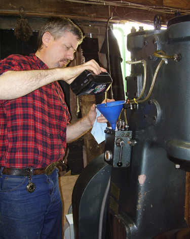
 Filling
the oil reservoir. A fill plug is located on top of the oiler manifold. Remove
the fill plug and insert a funnel in the fill port. A fine wire mesh screen has
been installed in the fill port to catch any dirt or debris that may accidentally
fall into the reservoir. The screen is very small and fragile, be careful not to
damage it with the funnel. Add oil to the reservoir. Note that the screen is very
fine and will cause the tank to fill very slowly, so add oil slowly and be careful
to seal the spout of the funnel tightly in the fill port to prevent leaking or
spilling of oil. Clean the top of the reservoir. Re-install the fill plug finger
tight. Be sure that the breather hole in the fill plug is clean so that it will
allow natural aspiration of the reservoir.
Filling
the oil reservoir. A fill plug is located on top of the oiler manifold. Remove
the fill plug and insert a funnel in the fill port. A fine wire mesh screen has
been installed in the fill port to catch any dirt or debris that may accidentally
fall into the reservoir. The screen is very small and fragile, be careful not to
damage it with the funnel. Add oil to the reservoir. Note that the screen is very
fine and will cause the tank to fill very slowly, so add oil slowly and be careful
to seal the spout of the funnel tightly in the fill port to prevent leaking or
spilling of oil. Clean the top of the reservoir. Re-install the fill plug finger
tight. Be sure that the breather hole in the fill plug is clean so that it will
allow natural aspiration of the reservoir.
Oil weight requirements. The oiler requires high oil viscosity to function properly - ISO 220 recommended (approximately 50 to 60 weight). Original recommendation called for Chevron Machine Oil AW 220. This oil has recently changed names and is now called Chevron Rando HD 220. Alternate names include Texaco Rando HD 220 and Chevron/Texaco Rando HD 220. Using low weight/low viscosity oil will cause poor oiler performance or a flow reversal malfunction. When filled with the correct weight of oil, the oiler works well.
How much oil is needed to fill the oiler reservoir? The quantities of oil quoted here are for the author's STC-88 air hammer. Total capacity of the oil reservoir when empty is approximately 27 (US) ounces. When a bubble appears at the top of the sight glass, approximately 20 (US) ounces of oil is needed to fill the reservoir. If the bubble appears in the middle of the sight glass, roughly 23 (US) ounces will be needed to fill the reservoir to full again. 28 ounces is equal to 1 (US) quart.
HINT: To avoid over-filling a funnel and spilling oil on the reservoir, fill a clean empty motor oil container with hammer oil, and use the index marks on the side of the container to measure the volume of oil poured into the funnel.
Re-establishing priming pump oil flow after low oil level has occurred. There are two methods for re-establishing oil flow and these methods are similar, but with small differences, to those methods described previously in the paragraph titled "Operating the priming pump."
Method #1 assumes that the blacksmith has recently stopped hammer operation to re-fill the reservoir with oil. The metering knobs are already open and set for proper oil flow. Refill the reservoir with oil and then push and pull the priming handle as many times as it takes until the drip domes fill with oil. Hold the priming handle fully inward and fully outward for two seconds each time that the handle is pushed and pulled. The check valves move slowly and require two seconds to close after the priming handle is actuated in each direction. The restricted condition of the metering knobs will slow the flow of oil, and as oil begins to refill the oiler system, a small resistance will be felt against the further pushing and pulling of the priming handle. Priming pump oil flow is re-established when oil begins to fill the drip domes.
Method #2 is best when metering valves were closed previously or when method #1 doesn't appear to work. Open the metering valves wide open (1 full turn counter-clockwise). Refill the reservoir with oil and then push and pull the priming handle as many times as it takes until the drip domes fill with oil. Oil will quickly flood the drip domes and no resistance will be felt on the priming handle because the metering valves are wide open and cause no restriction to oil flow. Remember to hold the priming handle fully inward and fully outward for two seconds each time that the handle is pushed and pulled. The check valves move slowly and require two seconds to close after the priming handle is actuated in each direction. Priming pump oil flow is re-established when oil begins to fill the drip domes.
After priming pump oil flow has been re-established, continue priming the oiler system in preparation for hammer run as described earlier in the paragraph titled "Operating the priming pump."
NOTE: If the methods described here for re-establishing oil flow fail to bring the oiler back into normal operation, check that the metering valves are open, proper weight of oil is being used, and that the oil reservoir has sufficient oil level to operate the priming pump (no bubble in oil level sight glass).
#3. Drip Oiler - Description of Design and Function
 The
priming pump. The body of the priming pump is cast as an integral part of the
reservoir tank- the priming pump is located at the bottom inside the tank. Check
valves (one-way valves) inside the priming pump direct oil flow through the pump
body. A plunger and return spring are installed inside the pump. The plunger
provides the necessary pumping action as the priming handle is actuated. Pulling
outward on the priming handle forces oil through the system, and pushing inward on
the handle refills/recharges the priming pump. The return spring pushes the
plunger and priming handle back to the refilled/recharged position after the
blacksmith releases the priming handle. A collar (cover plate) and gasket are
fitted around the plunger to seal the top of the pump chamber. The gasket provides
an oil tight seal between only the collar and the top of the pump chamber. There
are no elastic seals around the plunger or inside the priming pump. Proper sealing
and lubrication of the plunger is dependent on oil viscosity and close proximity
of fit between the moving parts of the priming pump.
The
priming pump. The body of the priming pump is cast as an integral part of the
reservoir tank- the priming pump is located at the bottom inside the tank. Check
valves (one-way valves) inside the priming pump direct oil flow through the pump
body. A plunger and return spring are installed inside the pump. The plunger
provides the necessary pumping action as the priming handle is actuated. Pulling
outward on the priming handle forces oil through the system, and pushing inward on
the handle refills/recharges the priming pump. The return spring pushes the
plunger and priming handle back to the refilled/recharged position after the
blacksmith releases the priming handle. A collar (cover plate) and gasket are
fitted around the plunger to seal the top of the pump chamber. The gasket provides
an oil tight seal between only the collar and the top of the pump chamber. There
are no elastic seals around the plunger or inside the priming pump. Proper sealing
and lubrication of the plunger is dependent on oil viscosity and close proximity
of fit between the moving parts of the priming pump.
Priming pump characteristics and theory of operation. The priming pump induces oil flow by displacing oil from the pump chamber into the flume capillary. Under construction drawings needed here. The pump plunger has a 'T' shape with the large end fitted inside the pump chamber, and the long stem extending up through the collar to the forked yoke. The collar fits closely around the plunger stem to help seal oil inside the priming pump chamber but, the plunger piston fits very loosely inside the pump bore. There are no valves or passageways to relieve oil pressure between the 'T' of the plunger and the top of the pump chamber and collar. The loose fit of the plunger inside the pump bore allows oil to move freely around the 'T' of the plunger and thus prevent hydraulic lock from occurring. As the priming handle is pulled, the pump plunger is forced down into the pump chamber, taking up more volume inside the pump bore- and thus causing an increase in pressure inside the pump chamber which in turn, forces the oil to flow out of the pump chamber ahead of the advancing plunger, and into the flume towards the hammer cylinders. When the priming handle is pushed in, the plunger is raised up out of the pump chamber- causing a low pressure condition, and atmospheric pressure inside the oil reservoir forces oil to flow into the pump chamber and fill the cavity of the pump chamber underneath the plunger. The pumping action is a result of positive displacement that is induced by lifting and lowering the plunger inside the pump bore.
 Rocker
shaft & yoke transfer motion of priming handle to pump plunger. The priming
pump handle is mounted to the end of a rocker shaft, the shaft inserted through a
plate and rubber gasket and through a bearing journal in the top corner of the
reservoir. The rubber gasket seals and prevents the oil inside the reservoir from
leaking out around the rocker shaft. A yoke with a forked slot is mounted to the
rocker shaft inside the reservoir - above the priming pump. As the priming handle
is pulled, the yoke rotates downward - pushing the pump plunger down into the pump
bore. Pushing the priming handle rotates the yoke upward- lifting the plunger in
the pump bore. The plunger is connected to the yoke with a pin and tubular
bushing. The bushing acts as a roller and a spacer, reducing wear, and allowing a
smooth rolling/sliding action between the yoke and pump plunger. The distance or
length between the end of the yoke and the pump plunger connection continually
changes as the yoke alternately lifts and lowers the plunger. The forked slot in
the yoke allows a sliding connection that absorbs changes in length between the
yoke and pump plunger- preventing binding that would otherwise result from a more
rigid or fixed connection.
Rocker
shaft & yoke transfer motion of priming handle to pump plunger. The priming
pump handle is mounted to the end of a rocker shaft, the shaft inserted through a
plate and rubber gasket and through a bearing journal in the top corner of the
reservoir. The rubber gasket seals and prevents the oil inside the reservoir from
leaking out around the rocker shaft. A yoke with a forked slot is mounted to the
rocker shaft inside the reservoir - above the priming pump. As the priming handle
is pulled, the yoke rotates downward - pushing the pump plunger down into the pump
bore. Pushing the priming handle rotates the yoke upward- lifting the plunger in
the pump bore. The plunger is connected to the yoke with a pin and tubular
bushing. The bushing acts as a roller and a spacer, reducing wear, and allowing a
smooth rolling/sliding action between the yoke and pump plunger. The distance or
length between the end of the yoke and the pump plunger connection continually
changes as the yoke alternately lifts and lowers the plunger. The forked slot in
the yoke allows a sliding connection that absorbs changes in length between the
yoke and pump plunger- preventing binding that would otherwise result from a more
rigid or fixed connection.

 Priming
pump oil passages. The vertical flume cast into the rear wall of the reservoir
tank contains a large oil capillary that conducts oil from the priming pump to the
distribution manifold. The flume capillary was drilled vertically down through the
inside rear corner of the priming pump where the flume and pump merge together,
and is visible as a large 5th hole in the middle of the back wall of the
disassembled oiler body. Two holes are drilled horizontally through the side of
the reservoir and priming pump body - the first hole drilled all the way through
the front of the pump body into the reservoir tank- the second hole drilled
through the rear of the pump body and connecting with the oil capillary in the
flume. A third hole is drilled horizontally through the middle of the pump from
the rear - connecting both of the holes previously drilled through the pump from
the side. The pump chamber is bored vertically in the middle of the pump body -
the chamber terminating immediately at a depth that connects (intersects) with the
small hole that was drilled through the pump from the rear. All exposed outer
holes are plugged and sealed.
Priming
pump oil passages. The vertical flume cast into the rear wall of the reservoir
tank contains a large oil capillary that conducts oil from the priming pump to the
distribution manifold. The flume capillary was drilled vertically down through the
inside rear corner of the priming pump where the flume and pump merge together,
and is visible as a large 5th hole in the middle of the back wall of the
disassembled oiler body. Two holes are drilled horizontally through the side of
the reservoir and priming pump body - the first hole drilled all the way through
the front of the pump body into the reservoir tank- the second hole drilled
through the rear of the pump body and connecting with the oil capillary in the
flume. A third hole is drilled horizontally through the middle of the pump from
the rear - connecting both of the holes previously drilled through the pump from
the side. The pump chamber is bored vertically in the middle of the pump body -
the chamber terminating immediately at a depth that connects (intersects) with the
small hole that was drilled through the pump from the rear. All exposed outer
holes are plugged and sealed.
Priming pump internal check valves. Two check valves are installed inside the priming pump. The first check valve is installed between the reservoir oil passage, and the pump chamber inlet oil passage. The second check valve is installed between the pump chamber outlet oil passage, and the flume capillary. These two check valves direct oil flow through the priming pump while the pump is being actuated, but they do not otherwise effect oil flow during normal atmospheric oiler operation. The first check valve (between the reservoir oil passage and the priming pump) allows oil from the reservoir to fill/refill the priming pump, but blocks oil from flowing back into the reservoir while the pump is being actuated. The second check valve (between the priming pump and flume capillary) allows oil to flow into the flume capillary, but blocks oil from being drawn backward from the flume to the pump while the priming pump is refilling with oil. Oil flow direction through the check valves is identical during both normal atmospheric operation and priming pump actuations.
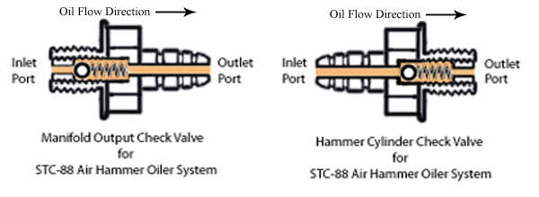 What
is a check valve? A check valve is a special hydraulic or pneumatic device
that allows (by mechanical action) fluid/gas to flow freely in one direction but
limits or blocks flow in the opposite direction. A ball and spring are the most
common form of check valve and this design is used in the Striker STC-88 hammer
oiler. In the example shown here (see diagram), oil enters the inlet port and
under very light pressure (atmospheric pressure only), forces the ball off its
seat and flows around the ball, through the spring, and out through the outlet
port. If oil were to stop flowing, or try to reverse direction and flow backwards,
the spring will push the ball back against its seat and thus blocking or
preventing any reversal of oil flow. Check valves make this oiler work so take
good care of them.
What
is a check valve? A check valve is a special hydraulic or pneumatic device
that allows (by mechanical action) fluid/gas to flow freely in one direction but
limits or blocks flow in the opposite direction. A ball and spring are the most
common form of check valve and this design is used in the Striker STC-88 hammer
oiler. In the example shown here (see diagram), oil enters the inlet port and
under very light pressure (atmospheric pressure only), forces the ball off its
seat and flows around the ball, through the spring, and out through the outlet
port. If oil were to stop flowing, or try to reverse direction and flow backwards,
the spring will push the ball back against its seat and thus blocking or
preventing any reversal of oil flow. Check valves make this oiler work so take
good care of them.
There are two types or applications of check valves. The first is a completely self-contained unit that is installed or connected to tubing or plumbing in the hydraulic/pneumatic system. The hose fittings threaded into the drip oiler manifold and hammer cylinders are self-contained check valves. The second application of check valve is an internal or integral check valve this is installed inside of, or machined inside of, the hydraulic/pneumatic system housing. Internal/integral check valves can be seen or inspected only after opening or disassembling the hydraulic/pneumatic system housing. Two integral check valves are installed inside the priming pump housing on the STC-88 oiler.
 Oil
seepage in check valves. The hard (inelastic) surfaces of the check valve ball
and seat, cannot be made to fit with absolute perfection. With that said, it
becomes apparent that there will always be a small amount of seepage or leakage of
oil through the check valve, and the volume, or rate of oil leakage, will vary
depending on viscosity and pressure of the oil that seeks to flow in reverse
direction through the check valve. This leakage is very, very small and does not
effect the oiler system during normal operation as long as the proper weight of
oil is used. With the hammer at rest, oil will (over a period of hours) drain back
down into the reservoir. This is why a drip oiler must be primed before use after
the hammer has been idled for more than a couple of hours. Lower viscosity
(lighter weight) oil will seep in reverse direction through the check valve more
easily than higher viscosity (heavier weight) oil.
Oil
seepage in check valves. The hard (inelastic) surfaces of the check valve ball
and seat, cannot be made to fit with absolute perfection. With that said, it
becomes apparent that there will always be a small amount of seepage or leakage of
oil through the check valve, and the volume, or rate of oil leakage, will vary
depending on viscosity and pressure of the oil that seeks to flow in reverse
direction through the check valve. This leakage is very, very small and does not
effect the oiler system during normal operation as long as the proper weight of
oil is used. With the hammer at rest, oil will (over a period of hours) drain back
down into the reservoir. This is why a drip oiler must be primed before use after
the hammer has been idled for more than a couple of hours. Lower viscosity
(lighter weight) oil will seep in reverse direction through the check valve more
easily than higher viscosity (heavier weight) oil.
The oil manifold. The top cover of the reservoir contains an oil metering manifold to meter and distribute oil to each output tube or zone. The main oil gallery is drilled through the middle of the manifold from the rear. Oil enters the main oil gallery by way of a short capillary hole that connects with the flume capillary in the reservoir tank. Zone oil supply passages are drilled through the sides of the manifold - connecting the main oil gallery with the metering galleries. Metering galleries are drilled from the front of the manifold, through the zone oil supply passages, and finally terminating in a connection with the drip tubes underneath the drip domes. The working end of each metering valve consists of a needle and seat installed in the metering gallery between each zone oil supply and drip tube passage. Output oil passages are drilled through the sides of the manifold (underneath) the output check valves, each output passage ending underneath its corresponding drip dome (left drip dome- left output check valve fitting, and right drip dome- right output check valve fitting). Outlet ports are drilled down through the upper surface of the drip dome gallery- connecting each drip dome with the output passage below it. And finally, the output oil ports are drilled in the top of the manifold, connecting the ends of the output passages with the hammer cylinder oil tubes. The output ports are threaded to receive the output check valves. All open passages along the sides and rear edges of the manifold are plugged and sealed after machining is complete.
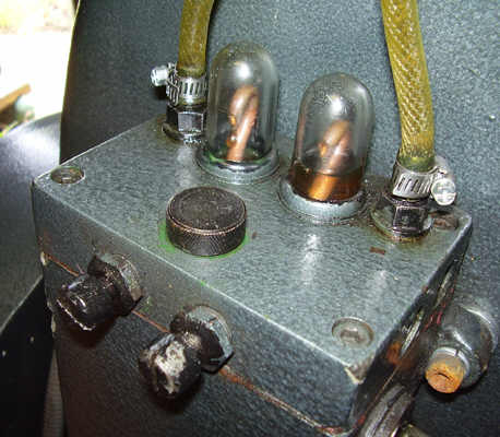 Metered
oil outputs. There are two metered oil output zones - left zone/compressor
cylinder and right zone/ram cylinder. Volume of oil flow in each zone is
controlled by adjusting the metering valves to increase or restrict flow as
desired.
Metered
oil outputs. There are two metered oil output zones - left zone/compressor
cylinder and right zone/ram cylinder. Volume of oil flow in each zone is
controlled by adjusting the metering valves to increase or restrict flow as
desired.
Drip domes and visible oil flow. A pair of transparent (see-thru) drip domes on top of the reservoir/manifold allow the hammer operator to visually monitor oil flow and operation of the oiler. As long as the oiler system and tubing are in good working order (no leaks), oil flowing through the drip domes indicates the volume of oil flow feeding into the hammer cylinders.

 External
check valves & oil tubes. External check valves direct oil flow in one
direction- towards the hammer cylinders. There are four external check valves used
on the STC-88 oiler - two output checks located on top of the oiler, and two input
checks threaded into the sides of the hammer cylinders (one in each cylinder).
Output check valve fittings on the rear corners of the reservoir prevent oil from
flowing backward into the reservoir manifold. The output check valves allow oil to
flow one way - out through the hose side of the valve. Input check valves
(one threaded into the side of each hammer cylinder) prevent air in the hammer
cylinders from being forced into the oil tubes while the hammer is running. Input
check valves allow the oil to flow one way - into the hammer cylinder. The hammer
cylinder check valve insert threads, are spiked (threads damaged with a punch to
prevent the insert from loosening) to prevent the valve parts from loosening and
later falling into the hammer cylinders. For this reason the hammer cylinder check
valves cannot be disassembled.
External
check valves & oil tubes. External check valves direct oil flow in one
direction- towards the hammer cylinders. There are four external check valves used
on the STC-88 oiler - two output checks located on top of the oiler, and two input
checks threaded into the sides of the hammer cylinders (one in each cylinder).
Output check valve fittings on the rear corners of the reservoir prevent oil from
flowing backward into the reservoir manifold. The output check valves allow oil to
flow one way - out through the hose side of the valve. Input check valves
(one threaded into the side of each hammer cylinder) prevent air in the hammer
cylinders from being forced into the oil tubes while the hammer is running. Input
check valves allow the oil to flow one way - into the hammer cylinder. The hammer
cylinder check valve insert threads, are spiked (threads damaged with a punch to
prevent the insert from loosening) to prevent the valve parts from loosening and
later falling into the hammer cylinders. For this reason the hammer cylinder check
valves cannot be disassembled.
#4. Drip Oiler - Oil Flow Path Summary
Metering valves must be open to allow oil to flow. The oil flow path described here is always the same irregardless of whether the priming pump is being actuated or the oiler is in normal atmospheric operation.
Initial path of oil flow. Reservoir oil first enters the drip oiler system through a small inlet passage drilled through the priming pump housing inside the reservoir. The oil passes through a check valve and turns to flow through the pump inlet passage into the priming pump chamber. Oil from the pump chamber flows out through the pump outlet passage and turns to flow through a second check valve leading to the flume capillary in the back of the reservoir tank. The oil flows up and out of the top of the flume into the main oil gallery inside the reservoir cover/manifold.
 Manifold
- Oil flow path. Oil from the reservoir flume capillary fills the main oil
gallery in the manifold, and then flows through each of the zone oil supply
passages to the metering galleries. After passing through the metering valves, oil
enters the drip tube supply passages and flows through the drip tubes. At this
point, oil can be seen dripping (or flowing) from the drip tubes and filling the
drip domes. Oil exits the drip domes through the ports in the bottoms of the
domes, then flows through the output passages towards the output check valves. Oil
exits the manifold through the output check valves - flows through the oil supply
tubes to the hammer - and finally flows through the input check valves and into
the hammer cylinders. This is the end of the oil flow path for the atmospheric
drip oiler system.
Manifold
- Oil flow path. Oil from the reservoir flume capillary fills the main oil
gallery in the manifold, and then flows through each of the zone oil supply
passages to the metering galleries. After passing through the metering valves, oil
enters the drip tube supply passages and flows through the drip tubes. At this
point, oil can be seen dripping (or flowing) from the drip tubes and filling the
drip domes. Oil exits the drip domes through the ports in the bottoms of the
domes, then flows through the output passages towards the output check valves. Oil
exits the manifold through the output check valves - flows through the oil supply
tubes to the hammer - and finally flows through the input check valves and into
the hammer cylinders. This is the end of the oil flow path for the atmospheric
drip oiler system.
Used oil is captured and recycled by the recovery method described in the next chapter - Used oil recovery.
#5. Drip Oiler - Disassembly, Repair and Maintenance


Draining oil out of reservoir tank. A drain plug is installed in the bottom of the reservoir. Remove the drain plug to drain oil.
Disassembling the reservoir for maintenance - original factory installation. Reservoirs that were originally installed by the factory have no spacers between the reservoir body and hammer frame. It is necessary to remove the reservoir from the hammer frame because the core hole plugs in the rear of the reservoir are pressed tightly against the hammer frame during original installation - preventing disassembly while the reservoir is mounted on the hammer. Before removing the reservoir from the hammer, drain the reservoir tank by removing the drain plug in the bottom of the tank, and disconnect the oil hoses from the check valve fittings on the top of the manifold. When reinstalling the reservoir on the hammer frame, be sure that the reservoir is fully assembled before bolting back onto the hammer frame.
Disassembly of reservoir. There are four socket head screws holding the reservoir cover/manifold in place (one screw in each corner of the cover). After removing these screws, carefully pry the manifold off the tank-being careful to avoid tearing the gasket seal between the main body and manifold cover, and be careful to avoid damaging the fine wire-screen mesh that hangs down inside the reservoir tank. The plugs in the side edges of the manifold should not be removed for any reason. They plug the machined holes that were part of the manufacturing process and are sealed to prevent oil leaks and/or seepage.

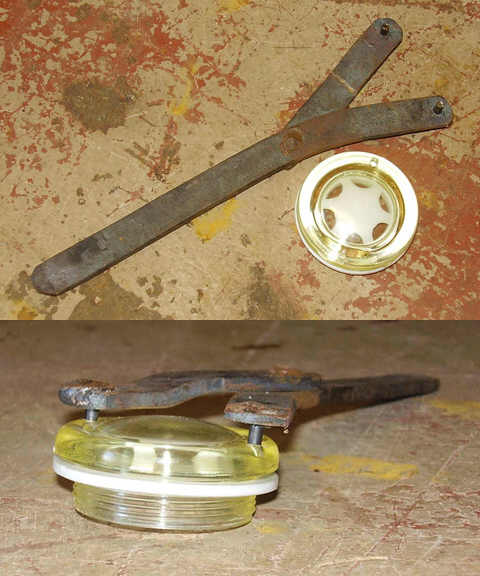 Oil
level sight glass. The oil sight glass has a 42mm x 1.5mm threaded barrel and
rubber seal, and is threaded into the front of the reservoir tank. A spanner
wrench is used to remove and install the plastic sight glass. I made my spanner
wrench from a small piece of flat steel with 1/8" (2.5mm) pins welded to the ends.
New plastic sight glasses can be obtained from Striker Tool Company. Expensive
aluminum sight glasses with scratch resistant glass can be obtained from J.W.
Winco and from MSC Industrial.
http://www.jwwinco.com/ and
http://www1.mscdirect.com/
Oil
level sight glass. The oil sight glass has a 42mm x 1.5mm threaded barrel and
rubber seal, and is threaded into the front of the reservoir tank. A spanner
wrench is used to remove and install the plastic sight glass. I made my spanner
wrench from a small piece of flat steel with 1/8" (2.5mm) pins welded to the ends.
New plastic sight glasses can be obtained from Striker Tool Company. Expensive
aluminum sight glasses with scratch resistant glass can be obtained from J.W.
Winco and from MSC Industrial.
http://www.jwwinco.com/ and
http://www1.mscdirect.com/
Drip Domes. Drip domes are threaded into the top of the manifold. If they become broken, the hole can be cleaned out and new drip domes threaded in place. Drip domes can be obtained from Striker Tool Company.
Check valves are NOT interchangeable. To determine which direction the oil flows through the valve, clean the valve, blow through it and note which direction the valve allows air to pass. Manifold check valves and hammer cylinder check valves are NOT interchangeable. Don't install them in the wrong component- they will block oil flow if mixed up.
 Used
oil catch containers. The smaller air hammers (STC-55 & STC-88) are a simple
design such as might have been common around the early 1900's. There is no pump
that would have returned oil from the sump to the oiler. Instead the oil simply
drains out of the sump through a hole in the frame below the compressor cylinder.
On the author's air hammer, plastic oil containers are used to catch oil that
drains from the sump. The oil containers shown here (photo at right) are typical
1-Quart (US measure) as used for automobile motor oil. The recovery oil containers
are oriented so that the sight strip is facing forward and the oil level inside
the container is conveniently visible to the operator while standing in front of
the hammer. The drain tube from the hammer sump is fitted through a hole in the
cap of the recovery container. A fabricated bracket was welded to the side of the
workstand (below the sump drain) to support a pair of these plastic oil catch
containers. After one container is full, the tube and cap are moved to the second
container. Used oil can then be added back to the drip oiler or discarded at a
recycling center.
Used
oil catch containers. The smaller air hammers (STC-55 & STC-88) are a simple
design such as might have been common around the early 1900's. There is no pump
that would have returned oil from the sump to the oiler. Instead the oil simply
drains out of the sump through a hole in the frame below the compressor cylinder.
On the author's air hammer, plastic oil containers are used to catch oil that
drains from the sump. The oil containers shown here (photo at right) are typical
1-Quart (US measure) as used for automobile motor oil. The recovery oil containers
are oriented so that the sight strip is facing forward and the oil level inside
the container is conveniently visible to the operator while standing in front of
the hammer. The drain tube from the hammer sump is fitted through a hole in the
cap of the recovery container. A fabricated bracket was welded to the side of the
workstand (below the sump drain) to support a pair of these plastic oil catch
containers. After one container is full, the tube and cap are moved to the second
container. Used oil can then be added back to the drip oiler or discarded at a
recycling center.
 Under
construction.
Under
construction.
 Air
hammer rams are stowed in the raised position when the hammer is not running.
There are two types of exposure that will cause premature wear of the ram. These
are dust and humidity (condensation). Both dust and water/condensation are
attracted to the oily surface of the ram. Abrasive dust will slowly grind away the
surface of the ram. Humidity penetrates beneath the oil coating and corrodes the
surface of the ram. It may not be possible to completely prevent these kinds of
exposure, but hammer owners can dramatically reduce abrasion and corrosion by
stowing the ram in the raised position.
Air
hammer rams are stowed in the raised position when the hammer is not running.
There are two types of exposure that will cause premature wear of the ram. These
are dust and humidity (condensation). Both dust and water/condensation are
attracted to the oily surface of the ram. Abrasive dust will slowly grind away the
surface of the ram. Humidity penetrates beneath the oil coating and corrodes the
surface of the ram. It may not be possible to completely prevent these kinds of
exposure, but hammer owners can dramatically reduce abrasion and corrosion by
stowing the ram in the raised position.
A simple wooden block. The simplest method for stowing the ram is to place a large wooden block between the raised dies, and then stop the machine- allowing the ram to fall onto the wooden block. The block keeps the ram raised high up in the cylinder where there is little or no dust, and exposure to humidity and condensation is reduced. The block seen in the photo here is of oak and measures 8-1/2 inches (21.5 cm) tall, 3-1/2 inches (9 cm) x 6 inches (15 cm).
Initial inspection. Before operating the hammer I attempted to grease the crank shaft bearings and pitman bearing using the existing grease zerks. The zerks proved to be very poorly fitted and required replacing before grease could be applied to the bearings. For anybody reading this that isn't sure what I meant by poorly fitted zerks, it means that I expect to be able to force ALL grease into the bearing and not find grease flowing out around the sides of the zerk or all over the place. All grease needs to go to the bearing, and if a zerk does not allow for this then it must be replaced. It was necessary to replace the existing zerks with new ones. See the pictures at right.
Establish priming pump oil flow. I filled the oiler reservoir with oil and primed the oiler system as described in the Drip Oiler - Operating Instructions.
Lighter weight oil used for break-in. For break-in only, I used Sunoco ISO 46. I switched to a heavier weight after initially using about 1 gallon of lighter weight oil during break-in.
Hammer is shipped with preservative coating on machined surfaces. The preservative prevents rust from forming on the machined surfaces during shipment and storage. Oiler metering valves were opened wide for maximum oil flow during initial startup. Oil must be allowed to flow freely to dissolve and wash away the preservative coating on the machined parts inside the hammer. Some of the free oil will flow out of the front hammer cylinder onto the bottom die block and I kept rags nearby to wipe up the excess oil during break-in. Oil from the rear cylinder falls into the sump inside the hammer frame and drains out through a tube into a catch container.
Break-in involves operating the hammer with the ram reciprocating up and down almost a full stroke but not allowing the dies to strike. Drip oiler adjustment screws were opened wide so oil would flow freely during break-in operation. The large volume oil flow is for break-in purposes. A block was placed under the rear of the treadle and adjusted as needed to keep the hammer running by itself while I monitored hammer operation. It is wise to never allow a hammer to operate unless the operator is nearby. With the oiler running wide open, excess oil leaks out of both cylinders, and after the color of this leaking oil began to clear up, I adjusted the number of drips visible in the clear domes to about 20 to 25 drops per minute. Oil leakage continues to be dirty in color, so I let the hammer have lots of oil to clean itself during break in. Oil feed will be adjusted to about 8-12 drops per minute after hammer wear in.
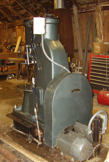
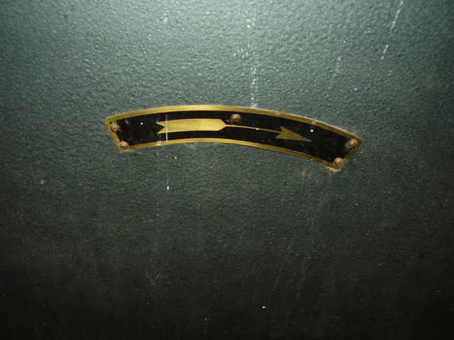 Check
direction of flywheel rotation. Rotation must match the direction of the arrow
placard that is riveted to the top of the flywheel cover. See the photo at right.
The rotation direction must be corrected if it does not match the arrow placard.
For more about this task, see problem #3 in the Troubleshooting section further
down this page.
Check
direction of flywheel rotation. Rotation must match the direction of the arrow
placard that is riveted to the top of the flywheel cover. See the photo at right.
The rotation direction must be corrected if it does not match the arrow placard.
For more about this task, see problem #3 in the Troubleshooting section further
down this page.
Trial run. First task with my new air hammer was to make a few simple tools. Beginning with a 1-1/2" x 1-3/4" bar I was able draw a 12" length x 1/2" thickness x 2-1/4" width in a single heat. This hammer replaced my old Little Giant 25lbs mechanical hammer and there is almost no comparison. The Little Giant would have taken more than a dozen heats to do the work that this hammer did in one single heat.
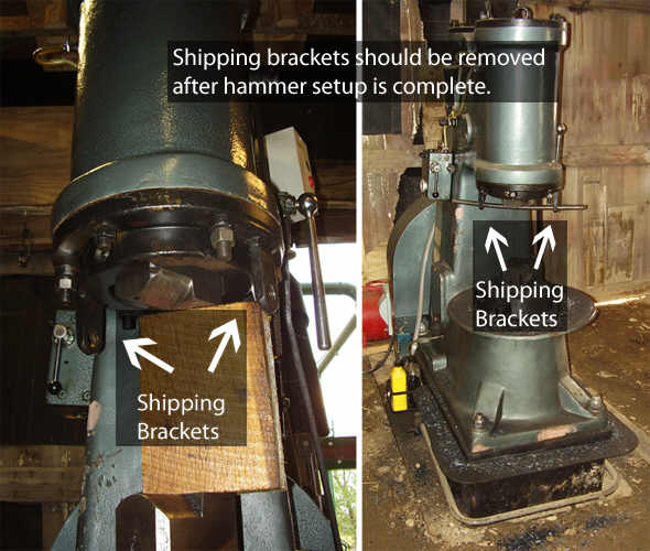 What
was the purpose of the shipping bracket? The shipping brackets were installed
by the manufacturer as a reliable way of securing the ram in the raised position
and protect the ram from corrosion during shipping. The shipping brackets serve no
other function.
What
was the purpose of the shipping bracket? The shipping brackets were installed
by the manufacturer as a reliable way of securing the ram in the raised position
and protect the ram from corrosion during shipping. The shipping brackets serve no
other function.
It is not entirely necessary to remove the shipping brackets after the hammer has been placed into service. The studs and hardware securing the shipping bracket are installed as though the hammer will be used with the shipping brackets left permanently in place. There will be no harm in using the hammer with the shipping brackets installed, and as can be seen in some of the photos on this page, the author kept the shipping brackets on his hammer for almost a year before removing them. However, there is a disadvantage to keeping the brackets installed. See the next paragraph for more on this.
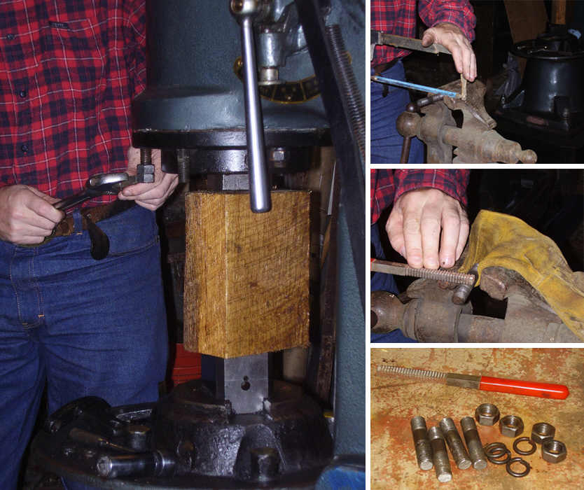 Shipping
brackets will partially obstruct access for large forgings and tools. The
shipping brackets extend approximately 2 inches (50 mm) below the collar of the
sealing unit underneath the ram cylinder- thus partially obstructing access to the
upper end of the open die gap. The blacksmith requires unobstructed access to the
full height or gap between the hammer dies while working with large forgings (such
as wide steel bars worked on edge) and tall tooling used on larger forgings. The
shipping brackets must be removed to work with large tools, and to allow wide bars
worked on edge. At right is a photo of the modified hammer with shipping brackets
removed and studs trimmed to length.
Shipping
brackets will partially obstruct access for large forgings and tools. The
shipping brackets extend approximately 2 inches (50 mm) below the collar of the
sealing unit underneath the ram cylinder- thus partially obstructing access to the
upper end of the open die gap. The blacksmith requires unobstructed access to the
full height or gap between the hammer dies while working with large forgings (such
as wide steel bars worked on edge) and tall tooling used on larger forgings. The
shipping brackets must be removed to work with large tools, and to allow wide bars
worked on edge. At right is a photo of the modified hammer with shipping brackets
removed and studs trimmed to length.
WARNING! Any mistakes made during this modification may result in changes in performance and damage to the hammer. Only a competent mechanic should make the modification described here. Get help! If you make a mistake, your machine may be damaged. This modification is not necessary and the hammer will perform well with shipping brackets left in place.
 MODIFICATION
- Removing shipping brackets. There are two ways to perform this task- on
the hammer, and off the hammer. I chose to remove the studs and finish the work
off the hammer. Here is how work proceeded. The shipping brackets were unbolted
and removed. The studs were inspected to be sure they were threaded fully into the
cylinder. I measured the difference in length of the short studs (the two studs
that were not used for the shipping brackets) and compared measurements with the
length of the long studs (the ones used with the shipping brackets). The long
shipping brackets studs were removed and trimmed with a hacksaw, sharp edges
dressed with a file, and threads were cleaned with a thread file. The shortened
studs were re-installed and tightened in the cylinder walls with light torque. The
original nuts and lock washers were then re-installed and tightened with light
torque. The completed job was then inspected to insure that all studs were uniform
in size. All studs and nuts were tightened using light torque - NOT high torque -
excessive torque could damage threads in the cast iron hammer frame. The shipping
brackets have been removed from the hammer in the photo at right.
MODIFICATION
- Removing shipping brackets. There are two ways to perform this task- on
the hammer, and off the hammer. I chose to remove the studs and finish the work
off the hammer. Here is how work proceeded. The shipping brackets were unbolted
and removed. The studs were inspected to be sure they were threaded fully into the
cylinder. I measured the difference in length of the short studs (the two studs
that were not used for the shipping brackets) and compared measurements with the
length of the long studs (the ones used with the shipping brackets). The long
shipping brackets studs were removed and trimmed with a hacksaw, sharp edges
dressed with a file, and threads were cleaned with a thread file. The shortened
studs were re-installed and tightened in the cylinder walls with light torque. The
original nuts and lock washers were then re-installed and tightened with light
torque. The completed job was then inspected to insure that all studs were uniform
in size. All studs and nuts were tightened using light torque - NOT high torque -
excessive torque could damage threads in the cast iron hammer frame. The shipping
brackets have been removed from the hammer in the photo at right.
 Safety
WEAR SAFETY GLASSES! The most important tool in the blacksmith's shop is safety glasses. Look closely at the photos at left. The smith always wears safety glasses while operating the hammer. In the photo at lower left, scale can be seen flying up off the scale pan due to shock and vibration during hammer operation. Everyone working with or near an air hammer should be required to wear safety glasses while the hammer is operating. During routine hammer operation this author has been sprayed with hot scale as a result of vibration, bending, welding, drawing, and also when oil and water was present on the hammer dies during forging. Other hazards include flying objects as hot iron was cut or tools broke under the air hammer. Despite all of these hazards there have been no serious injuries. Safety works! Safety glasses are a requirement in the author's shop - especially when the air hammer is in operation. Make safety a part of your work too! Good safety and work habits reduce or prevent injuries.
Keep all guards installed securely and correctly. The machine guards prevent the operator and other people from accidentally coming into contact with moving parts of the machine. The large flywheel guard covers the flywheel, drive belts, and the drive pulley on the motor. Machine guards must be maintained securely in place at all times. Motor and flywheel transmit a large amount of energy when the hammer is in operation. Severe injury may result if the guards are loose or missing during operation. Inspect guards each day before starting the hammer.
Beware of position of the work piece and tooling at all times while using the hammer. The force of hammer blows can cause the iron and hammer tooling to jump forcefully and unexpectedly while the workman is holding them. Tooling should be held in perfect vertical alignment on the hammer dies. Any tooling held at less then perfect alignment will be at risk of breaking or being sent flying across the shop. This rule also applies to the work piece that is being forged. The work piece must be held perfectly flat on the bottom die of the hammer, or the hammer will forcefully slam the work piece down or violently shifting the work piece. If the operator fails to maintain proper positioning of tooling or work piece on the hammer, then the work piece and/or tooling might suddenly be thrown forcefully by the force of the hammer blows - possibly causing injury to the operator and/or others nearby. Pay close attention to positions of all work pieces and tools that are being forged on the air hammer.
Oil or water on die surfaces will cause a burst of high pressure steam or gas resulting in scale being blown off the surface of the hot iron in all directions. It is normal for oil to drip from the front ram cylinder of an air hammer onto the bottom dies, and often after the hammer has been idled prior to forging, the first blows will result in a visible burst of flame and hot gases. Additionally any lubricants or coolants applied to dies prior to forging hot iron will result in a burst of flame and hot gases when forging begins again. It may be necessary to keep people away from the hammer during operation, or at least make them aware of the hazard described here.
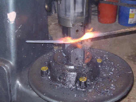 Remove
trip hazards and other entanglements from the work zone. The working area of
an air hammer is necessarily open and unobstructed to allow free-style work
methods. This open and unguarded condition also makes it possible for tools and
other objects, or the operator's body, to come into contact with hammer dies
accidentally. Keep the work area clear of any obstacle to the work. It is often
not possible to define the specific work area around the hammer - so stay alert to
the changing work/zone and warn others if they will be entering hammer forging
area.
Remove
trip hazards and other entanglements from the work zone. The working area of
an air hammer is necessarily open and unobstructed to allow free-style work
methods. This open and unguarded condition also makes it possible for tools and
other objects, or the operator's body, to come into contact with hammer dies
accidentally. Keep the work area clear of any obstacle to the work. It is often
not possible to define the specific work area around the hammer - so stay alert to
the changing work/zone and warn others if they will be entering hammer forging
area.
Lock out energy sources before performing maintenance. Lock it out! This machine can cause serious injury if it starts unexpectedly while the workman is performing service or maintenance on the hammer. Electrical service to the hammer should always be locked out before attempting to change dies, attach tooling to the hammer, and when working on any part that moves or stores any form of energy during operation. For anyone that doesn't understand what this means, enter these key words in your search engine- "Lock out tag out procedures". Shut off and lock electrical cut out switches with a lockout device and/or a padlock. If the machine uses a large outlet plug to connect to a welding outlet (like the hammer shown in the photos on this page), then use a plug & cord lock out device, and padlock, to prevent the plug from being inserted in an electrical outlet during machine maintenance.
Glendale Forge, made in Britain. Glendale Forge, Monk Street, Thaxted, Essex, England. Tel: 01371 830466 http://www.glendaleforge.co.uk/ High quality British-made tools for the blacksmith, ironworker, and farrier. Swages, cutters, and other forging tools for use hand forging and machine forging. Also offers new side-blast blacksmith's forges and parts.
Angele Schmiedetechnik, Bahnhofstrasse 23, Reinstetten, D-88416 Ochsenhausen, Tel ++49-(0)7352-92 26-0 Deutschland (Germany) http://www.angele.de/ Huge inventory of blacksmith's tools and machinery. Website is in three languages - German, French, and English. To access these languages, click the "Shop" link in the navigation bar at top of page, and then click on the little flag icon in the upper right corner of website to change language. There are two listings for swages under the Forging Tools navigation link. Click the second 'swages' link for power hammer and air hammer swages. Angele also offers 4 different brands of new air hammers for sale including; Kuhn, Say-Mak, Anyang, and AREF.
Kayne & Sons - Blacksmith's Depot https://www.blacksmithsdepot.com/ U.S. distributor for Off Centaur Forge swages and tools. Off Centaur Forge swage dies are made as first generation impressions by CNC die making machines rather than second generation impressions stamped into the die. Swage dies made from 4140 steel for toughness and very long wear. Kayne & Sons has been in business since the late 1950's as a blacksmith shop. Now known as the Blacksmith's Depot, they offer tools and machinery for blacksmiths. Visit their website their website to see photos of their modern blacksmith shop, or better yet, visit them in person and see their tools in action. Kayne & Sons Blacksmith Depot also offers new Iron Kiss pneumatic forging hammers.
Pieh Tool Company 661 E Howards Road, Suite J, Camp Verde, Arizona 86322 USA, Phone: 928-554-0700 http://www.piehtoolco.com/ Selling Victory Forge swages and tooling. Victory Forge is a blacksmith shop located near Pieh Tool Company store. Pieh Tool Company often partners with Victory Forge to offer classes for new blacksmiths. Victory Forge swages are made from mild steel. Visit Pieh Tool Company and see these tools in action. Pieh Tool Company also offers new Sahinler Air hammers for sale. Amy Pieh is the daughter of the late Bill Pieh - founder of Centaur Forge, so she has a long history of serving blacksmith's throughout the U.S.
Centaur Forge has two locations in the USA -Wisconsin & Texas. Centaur Forge - Wisconsin 117 N. Spring Street, Burlington, WI 53105 Phone: 262-763-9175 Hours: Monday - Friday, 7:30 a.m. - 6:00 p.m. Centaur Forge - Texas 1367 B Industrial Drive, New Braunfels, TX 78130 Phone: 830-627-2300 Hours: Monday - Friday, 7:30 a.m. - 6:00 p.m. http://www.centaurforge.com/ Centaur Forge currently has a limited supply of Off Center Forge brand spring swages and dies in stock for power hammers and air hammers. Off Center Forge brand spring swage dies made from 4140 steel for long wear. I spoke with a sales representative from Centaur in January of 2011, a large part of their of power hammer swage inventory has been put on close-out sale, and when this inventory is gone, it will not be replaced or reordered until the economy improves.
Making hammer tools and swages, I currently use 4140 and 4340 oil hardened molybdenum alloy steels to make all of my hammers and hammer tools. This family of steels is also used by other tool makers and manufacturers. Handles can be made from 5/16 inch or 3/8 inch round round mild steel for light weight hammer tools (under 3 lbs. - 2.5 k.g.). Heavier tools would of course require larger handles. The handles are kept as thin as possible to absorb shock and concussion. My earliest tools made 25 years ago, were made from 4132 and I depend on these anvil and hammer tools yet today. I recommend the 4140 and 4340 for hammer tools for hardness, toughness, and long wear. As an example of long wear, my leaf stamp swages were made from 4140 and after forging approximately 1400 leaves - they still show no signs of any wear at all!
See the Forging Hammers Resources page http://www.beautifuliron.com/gs_forging_hammer_resources.htm for a small but growing collection of books and other resources for training and instruction for working with forging hammers.
Warning! Electrical power must be locked out before working on electrical components or before opening and removing guards and access panels! Working with energized electrical systems can cause serious injury or death. It is recommended that this work be performed by trained and experienced workmen.
There are several problems that the new hammer owner is likely to encounter. I encountered some of these during setup of the hammer on this page. Fortunately I had experience wiring electrical motors for industrial applications. But if the new hammer owner isn't proficient in electrical work in the shop, these can be impossible to solve. Here are some common problems and solutions:
1.) PROBLEM. Motor starter relay operates (pulls in and seals) correctly when start button is pushed, but motor does not energize (one leg of the electrical circuit is hot and the other leg is open). For 240v single phase only.
This actually happened to me- my motor starter had been wired incorrectly at the factory - one of the wires had been connected to the wrong terminal on the motor starter contactor.
CAUSE: If the black jumper wire is connected from T2 at the bottom of overload relay, to the NO contacts at top of the motor start contactor, then there will be one open leg in the electrical circuit and the motor will not energize. In this configuration, the start contactor will pull in and seal magnetically when the start button is pushed, but the motor does not energize.
SOLUTION: The diagram (at near right) is of the motor starter relay and overload breaker on the author's hammer. The diagram (at far right) shows the correct wiring for 240v single phase. The NO contacts are the unused fourth set of connections at the right side of the starter relay. The photo shows exactly how it should look when the circuit is correctly wired for single phase 220v without an emergency stop line.
2.) PROBLEM. The starter contactor relay vibrates or rattles back and forth and will not remain magnetically engaged - tripping the circuit breaker in the overload device - and the motor does not come up to full speed. The motor appears to lack the large amount of torque required to start and operate an air hammer. (for 240v single-phase systems only)
CAUSE: Possible error might - one of the two hot wires has been mixed up with the ground or neutral wire, creating a 120v circuit by accident. If the wall outlet is known to be correct, then wires could have been mixed up in one or more areas including; 1.) inside the plug, 2.) inside the safety disconnect box on the hammer frame, 3.) inside the starter box.
HINT: It is very easy and very common to make errors while connecting wires, so inspect all wiring connections very carefully.
SOLUTION: Use a notepad to record all wire colors and connections, and compare with the original wiring diagram. Inspect and verify all wires and connections to determine if all wires and connections found in each box and plug - are in actually in agreement with the connections indicated by the wiring diagram. Correct or replace any misplaced or improper wiring connections.
3.) PROBLEM. Motor turns in wrong direction. Single phase or 3-phase.
There is only a 50%-50% chance of getting it right the first time when connecting the motor wiring. No harm done if it is backwards when first starting the hammer, but excess wear of compressor cylinder may occur if allowed to continue. Compare the rotation with the arrow placard riveted to the rear of the flywheel guard.
SOLUTION: To change the direction of flywheel rotation, simply swap two wires. Here's how;
Single phase: swap the #5 with the #8 wires that connect to the T-lead from the motor start contactor. This connection is made inside the box that is mounted to the side of the motor.
3-phase: swap two of the three T-leads and reconnect. The T-lead connections can be changed anywhere in the circuit - in the safety disconnect box, inside the starter contactor box, or inside the motor connection box on the side of the motor. NOTE: any time that work has been performed on shop wiring involving 3-phase circuits, the hammer flywheel rotation must be checked after electrical work is completed, because any changes to the main 3-phase circuit can and will result in 3-phase circuit changes at the hammer, and possible reversal of motor rotation at the hammer.
4.) PROBLEM. Motor makes a growling noise when energized, but does not turn. Three phase only!
CAUSE: One leg of the three phase power circuit to the motor, is open. A growling noise or loud buzzing noise at the motor, accompanied by non-rotation of a three phase motor, is the classic symptom of 'single phasing'. Three phase motors need all three legs in the circuit to operate. Cut one leg and the motor sits still and growls.
SOLUTION: Check any fuses or circuit breakers that supply power to the hammer. Replace open fuses, reset tripped circuit breakers. If fuses and circuit breakers were not blown or tripped then check wiring connections at motor, at the starter contactor, and at the safety disconnect panel. Check each leg of the power circuit individually to be sure all three legs are 'hot'. Disconnect and lock out electrical power, and fix any faulty or misplaced connections that are found. If a 'dead' phase leg is found on the supply side of the electrical service panel, contact an electrician or electric company for assistance.
 Throttle
Lock (Obsolete)
Throttle
Lock (Obsolete)The page is here: http://www.beautifuliron.com/gs_stc-88_throttle_stop.htm .
New Striker hammers do not need this modification! All of the smaller hammers now have this operation built into the machine and the larger hammers have always had this operating function.
Early versions of the smaller hammers arrived from the factory with only a simple throttle linkage and treadle lever. This was because of legal liability concerns by the manufacturer. Anyone that has tried to operate one of these hammers knows how awkward the throttle can be when transitioning between the raise position and the strike position. Much of the movement of the treadle is needed to simply lift the ram and then rotate the valving into the striking position. But only a small amount of throttle is needed to rotate the valves past the raise position and into the strike position. This was changed several years later. All new hammers now come equipped with a throttle detent that automatically raises the ram when the throttle (treadle) is released. Striker has upgraded throttles for older hammers. Some small hammers made by other manufacturers will continue to require the modification described on the throttle lock page.
My throttle stop design is a simple bracket and sliding bolt that is adjusted to hold the throttle in the strike position with a small reciprocating motion of the ram. Again, this modification is not needed on the modern Striker hammers.
New Striker Distribution. First the bad news: Striker air hammers are currently unavailable because the original U.S. distributor was bankrupt in what appears to have been part of the housing bubble financial mania. And now the good news: New Striker dies and parts will soon be available again. We will begin stocking new Striker dies and parts soon. Watch this page for important upcoming announcements concerning parts availability.
Old sale flyers. At left are two pages from a recent sale flyer from the Striker Tool company (out of business now). If I were to guess which of his hammers are the most popular as far as number of sales per unit, I would guess that it is the 55 and 88 pound hammers.
Ready-made workstands are also available. New hammer buyers will save a lot of time setting up their new hammers by purchasing the heavy pre-cast workstands instead of trying to build a workstand like the one shown on this webpage.
Striker hammers have heavier frames and anvil blocks. The Striker hammer frame is larger, thicker, and heavier than its competitor. The anvil block is much heavier than most other power hammers - translating into much more powerful blows to the iron during forging. The striking force (hit energy) figures stated by most distributors are identical, but these figures do not account for the actual striking power of hammers with increased or decreased ram/anvil weight ratios. The hit energy figures are a mathematical representation that was arrived at by comparing the speed and distance of ram travel and weight of the ram. The hit energy figures are not a true representation of actual forging capacity of the hammers. A hammer of a given size will forge with more force against a heavier anvil compared with a hammer that has a lighter anvil. Pound for pound, the Striker hammers hit harder than other hammers.
Striker hammers have larger open die gap. The open die gap on the Striker (11 inches) is taller than the competitors' hammer (9-1/8 inches) and allows large tools to be used to forge heavy bars with more force than a hammer with a shorter open die gap. This was a very important feature to me because I forge large bars and use large (tall) hammer tooling, the larger open die gap gives me the room to do this work.
For blacksmiths, air hammers are the only real choice today. Whichever your preferences for hammer model or manufacturer, you really can't go wrong when buying an air hammer from a reputable dealer. Air hammers strike with approximately 2-1/2 to 3 times the force compared with a mechanical hammer of the same ram weight. The larger open die gap on an air hammer allows larger bars and special tooling to be used, tooling that could not otherwise be used on mechanical hammers with their smaller open die gap. While it is true that a Little Giant power hammer is great for drawing thin bars such as knife makers work, the air hammer is designed for everything else in which a large of amount of plastic manipulation of heavy bars is needed. And today the price of a working air hammer is the lowest I have ever seen. Now is the time to buy an air hammer- because they might not be so cheap in the future.
Latest update: November 11, 2022

Page created February 02, 2004
Write ups needed--- Motor starter theory, die removal and installation
Photos needed--- Use of die removal tools, exploded view parts of steel workstand, all dimensioned drawings replace, lock-out devices.
Drawings needed--- priming pump oil flow, reservoir oil flow