Blowers, Bellows, Firepots, and Hearths
[Home] [Back
To The Forge Design] [Blowers,
Bellows, Firepots, & Hearths] [Forge
Bellows] [Chimneys]
[Steel Hoods] [Side
Blast Forge Tuyeres] [Tools
Racks & Storage] [Styles
Of Forges] [Planning
Layout of Hearth]
[Steel
Side-draft Forge and Hood Plans] [Brake
Drum Forges] [Costs
To Build]
Updated on
September 29, 2019.
A discussion of the different types of air blast systems used on blacksmith's
coal forges, and firepots or methods of supporting the fire, and styles of
hearths. March 19th, 2001.
The air blast
Bellows
Under construction. This page is undergoing a large rewrite (as are most
of the Forge Design series) and more material will be added and pages will be
cleaned up for easier reading and faster downloading as I have time to make
the changes. This page in particular is the subject of a very large addition
to come soon. I am out of time so writing is stalled.
The Pair of bellows
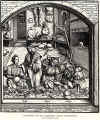 The
most common style of blacksmith's bellows depicted in medieval books and
manuscripts, is the pair of single-acting bellows. Click on the thumbnail
picture at left to see the 16th century woodcut depicting Emperor Maximillian
visiting the armoursmith Seusenhofer's workshop, from Charles Ffoulkes book
The Armourer And His Craft, printed by Dover Books ISBN 0-486-25851-3.
The
most common style of blacksmith's bellows depicted in medieval books and
manuscripts, is the pair of single-acting bellows. Click on the thumbnail
picture at left to see the 16th century woodcut depicting Emperor Maximillian
visiting the armoursmith Seusenhofer's workshop, from Charles Ffoulkes book
The Armourer And His Craft, printed by Dover Books ISBN 0-486-25851-3.
Pair of bellows section under construction.
The Great Bellows
 Towards
the 18th century a double acting bellows called a great bellows or compound
bellows, came into use. Combining the pair of bellows into a single great
bellows with an upper and lower chamber saved a large amount of space in the
shop
Towards
the 18th century a double acting bellows called a great bellows or compound
bellows, came into use. Combining the pair of bellows into a single great
bellows with an upper and lower chamber saved a large amount of space in the
shop
The upper chamber of the double acting compound style bellows (great
bellows) supplied the air blast to the fire in a steady or constant velocity.
Pressure of the blast air and velocity of the air into the fire was adjusted
by adding or removing weights placed on top of upper chamber board or hung
from hooks attached to the upper board. Air is trapped in the upper chamber by
a set of leather and wood flapper style check valves that are mounted on top
of the middle bellows board. Once trapped in the upper chamber, the air could
only exit through the nozzle hole carved through the wooden snout of the
bellows, and then through the air delivery piping to the tuyere and into the
fire. Leather sides and a leather hinge attaching the upper chamber board to
the nozzle allows the upper board to rise and fall in relation to the volume
of air trapped inside the upper chamber. A wooden spreader or rib is riveted
to the inside of the leather chamber wall and located mid-way between upper
chamber board and middle bellows board. The rib improves efficiency by
preventing the leather sides of the bellows from expanding outward while the
upper bellows chamber collapsed during used.
The lower chamber of the compound bellows forced air into the upper chamber
when the smith pulled the lever, and check valves inside the bellows allowed
them to trap air in proper directions. The bellows is quite large and takes up
a substantial amount of room in the shop. To conserve space, the bellows was
often mounted overhead. Still this takes up some substantial amount of room so
often the bellows was mounted above work benches or other areas which didn't
need much overhead room.
 Detailed
plans for building a great bellows can be found in the book The Blacksmith ~
Ironworker and Farrier by Aldron A Watson ISBN 0-393-30683-6.
Detailed
plans for building a great bellows can be found in the book The Blacksmith ~
Ironworker and Farrier by Aldron A Watson ISBN 0-393-30683-6.
The bellows began to be displaced as the sole source of air blast during
the 19th century when mass produced cast iron hand cranked and line shaft
driven blowers were manufactured. Today we use both modern electric blowers
and old hand cranked blowers to provide the air blast for our fires.
Centrifugal Blowers
The Hand-Cranked Blower
 The
blower moves air with centrifugal force by spinning at a high speed and
pushing air outward into the fan housing and into the air delivery pipe. A
series of gears or pulleys is used to step up the number of turns or rotations
the fan wheel makes for each turn of the crank. The blower case around a good
high volume machine is about 10 or more inches in diameter. Although some good
blower fan cases are smaller, most smaller blowers are too inefficient for
blacksmith's use. A good blower needs only about 1/2 revolution of the hand
crank per second to force a strong blast in the fire. Most blowers have some
type of mounting flange or lugs cast into their body or housing to allow
mounting to a frame or stand.
The
blower moves air with centrifugal force by spinning at a high speed and
pushing air outward into the fan housing and into the air delivery pipe. A
series of gears or pulleys is used to step up the number of turns or rotations
the fan wheel makes for each turn of the crank. The blower case around a good
high volume machine is about 10 or more inches in diameter. Although some good
blower fan cases are smaller, most smaller blowers are too inefficient for
blacksmith's use. A good blower needs only about 1/2 revolution of the hand
crank per second to force a strong blast in the fire. Most blowers have some
type of mounting flange or lugs cast into their body or housing to allow
mounting to a frame or stand.
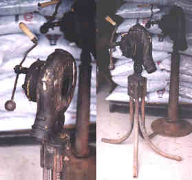
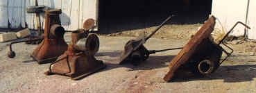
 There
are two types of blowers to discuss here. One is Omni-directional rotation and
the other is single direction of rotation. The Omni-directional blowers allow
the smith to turn the crank both clockwise and counter-clockwise for full
efficient blast of air. The cases of these types of blowers pictured above
left, swell to a tear drop shape at the air delivery connection.
What Photo? Photo missing?
There
are two types of blowers to discuss here. One is Omni-directional rotation and
the other is single direction of rotation. The Omni-directional blowers allow
the smith to turn the crank both clockwise and counter-clockwise for full
efficient blast of air. The cases of these types of blowers pictured above
left, swell to a tear drop shape at the air delivery connection.
What Photo? Photo missing?
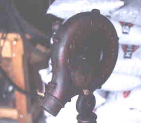
At right is an example of the type of blowers that were meant to be cranked
in one direction only. Note the difference in the shape of the fan case. The
fan must be rotated in one direction for most efficient air blast and moves
less air if turned the wrong direction.
Note that the style of crank rotation really doesn't matter except that
the smith needs to know which way the blower is turned if he/she wants to use
it or is testing one at a sale.
Soon after I began working as a blacksmith, I bought a new British Alcosa
F-70 hand cranked blower (photo at right) imported from England. These were
very expensive both because of importation costs and because cast iron is now
very expensive to produce. Modern blowers may still be available, but due to
high cost and lack of popularity they are no longer sold by Centaur Forge.
Smiths who attend farm auctions and heavy horse auctions can still find good
antique hand cranked blowers for sale.
Inspect Used blowers before purchase!
When buying a used blower, the first thing to inspect is the ease with
which the crank can be turned and anything that suggests damaged or broken
gears or bearings. Grinding noises or a rough or grating feel of the crank in
operation is reason enough to look for another blower. Check to see if air is
being delivered by the fan. Check for clogs such as bird nests, hornets nests
or other debris, damaged or loose gearing or fan blade attachment, and missing
or broken fan blades. If the crank will not turn, check to see if debris has
blocked or jammed inside the fan housing. If the crank does turn, but the fan
does not, check to see if the fan shaft is turning inside the fan hub - fan
hub loose on shaft.
If any of the following conditions appear then the blower is junk:
- broken gear case,
- broken fan housing,
- cracks running through bearing seats,
- grinding gears,
- gear teeth missing or rusted off,
- rusted out interior of gear case.
Note: Blowers with air pipes that are not wide open or
disconnected, will turn with more difficulty compared with those that are
connected to a tuyere pipe of a forge! This is because a fan that is moving
a maximum volume of air - will turn with more difficulty because it is doing
maximum work. This is the opposite of what most newbie smiths would expect.
Want an easy demonstration for yourself? Try blocking the output hole (or
intake hole) of the blower with your hand, and then crank it, and then
unblock the output hole and crank it again. The blower will be easier to
crank while blocking the intake or output hole, and more difficult to crank
when you take your hand off the output hole. A resistance to air flow
reduces the amount of work done by the blower, so the crank becomes easier
to turn when air flow is restricted - like it will be when properly
connected to a forge firepot. Think of the blower as though it is the motor
of a vacuum cleaner. When the vacuum hose is blocked, the vacuum motor
suddenly runs faster because the air (suction) has stopped moving through
the hose. The same is true when testing the forge blower.
Look at the condition of the mounting brackets to see if they are still
serviceable. If the brackets are broken off, you will need to build a
frame to clamp the blower body into, and the supporting frame must allow you
to oil and maintain the blower. Some blowers were supplied with stands and
very likely still have them since the owners would have bought them originally
to service an existing permanent forge. Other blowers may be sold alone and
this occurs if they were separated from a forge that they had originally been
mounted. And still other blowers may be sold with their original forge. If a
blower is being sold with a portable forge, look closely to see if it actually
fits the forge mounts provided. If the blower doesn't appear to mount easily
to the forge, then it might have come from a different source and will need a
mounting adapter or its own stand to be used with that forge. Don't let paint
fool you, many sellers will gladly paint something to make it look 'new' and
bring more money. Paint is cheap, broken blowers aren't.
Most blowers have cast fan blade hubs with sheet metal blades and missing
blades can be replaceable. However to remain balanced if one blade is
replaced, all must be replaced, and using a single method of attachment. Bent
handle iron can be straightened with little trouble and broken or worn out
wood hand-crank grips can be replaced.
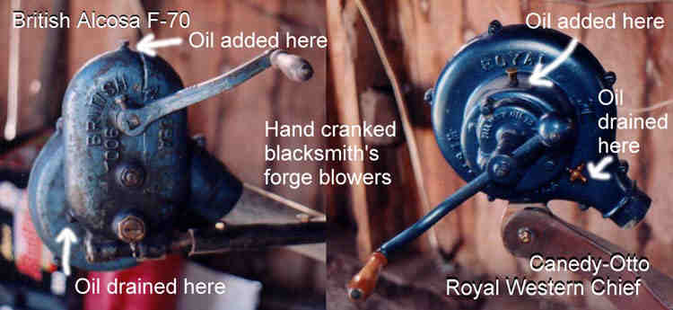 The
gear box of the hand cranked blower is filled with oil to the level of the
drain plug. The drain plug is mounted slightly up one side of the gear case so
static oil leaks will not seep so readily. To drain or change oil, the blower
is tilted towards the oil drain plug hole and allowed to drain. Any method of
mounting the blower must take into account that at some point in time the oil
may need changed and the blower will need to be moved to drain the oil.
Reasons for changing oil might include using different weights for summer and
winter use, especially if the blower is used in an unheated shop. After
draining the old oil from the gear case, the blower is raised level and it
should be noted that the drain plug is now located slightly up to one side as
in the photos above. With the blower level, the drain plug is left uninstalled
(or should be removed at this time) and oil is added through the top oil fill
hole until oil just starts to run out the drain plug hole. The plugs are then
reinstalled and the blower is ready for service.
The
gear box of the hand cranked blower is filled with oil to the level of the
drain plug. The drain plug is mounted slightly up one side of the gear case so
static oil leaks will not seep so readily. To drain or change oil, the blower
is tilted towards the oil drain plug hole and allowed to drain. Any method of
mounting the blower must take into account that at some point in time the oil
may need changed and the blower will need to be moved to drain the oil.
Reasons for changing oil might include using different weights for summer and
winter use, especially if the blower is used in an unheated shop. After
draining the old oil from the gear case, the blower is raised level and it
should be noted that the drain plug is now located slightly up to one side as
in the photos above. With the blower level, the drain plug is left uninstalled
(or should be removed at this time) and oil is added through the top oil fill
hole until oil just starts to run out the drain plug hole. The plugs are then
reinstalled and the blower is ready for service.
Restoring an antique blower.
I recommend this route for any blacksmith with the time. Many blowers need
only thorough cleaning inside to remove dried oil sludge and hardened deposits
from the teeth of the gearing and from the gear cases. By scraping with an awl
or screw driver, the hardened deposits can be removed from the inside of gear
teeth. Be careful here though, some blowers used one or more fiber or
cellulose gears to quiet the blower during use. Scraping will damage the fiber
gear teeth, so be gentle with the fiber gears. Alternate soaking in solvent
and scraping to help loosen deposits. Scrape all deposits off the inside gear
case and bearing supports as well. Thoroughly scrap and clean the seal seats
so the gear case can be counted on not to leak when reassembled. When cleaning
is finished use oil or thin white grease to lubricate bearings and gears
before final assembly. Seal areas must be free of all grease and lubricants
before final assembly. When all is scraped as much as you can, run through a
parts washer machine.
New wooden crank-handle grips can be made by a local wood turner or anyone
with access to a wood lathe. Custom turned handles are much more comfortable
and the turner can make better shapes than what came with the blower
originally. See the photo at left. The Alcosa F-70 blower at far left side of
the photo above, was bought new 20 years ago and always stored indoors, so the
handle is in good condition. The blower on the right side of the photo was
bought as an antique and the handle had rotted off. A new custom made handle
grip was installed. At one time I used to try to replace broken and rotted
wooden hand-crank grips with new ones I fashioned from file handles. I now
advise against this as wooden file handles are very uncomfortable to use and
work poorly.
Bent crank handles can be straightened with little effort. The wooden handle
grip is held on to the crank with a special retaining washer that is riveted
onto the end of the crank. Using a hammer and punch, and carefully working the
riveted section of the crank which holds the washer in place, the iron can be
upset inward enough to allow the washer to slide off the end. The wooden hand
grip is thus free to be removed or installed. The special retaining washer has
a small outside diameter so to fit inside the recessed hole inside the wooden
handle grip. A regular washer between the inside of crank and the handle grip
help keep the grip from chafing against the inside curve of the handle. With
the wooden handle grip and its retaining washer in place, the end of the crank
handle is peened out over the hole (clinched over the sides of hole) in the
retaining washer until the smith believes the washer won't come off again. A
recess in the end of the wooden grip keeps the sharp edges of the retaining
washer away from the hand when operating the blower. This recess is drilled
into the outside end of the new wood grip before assembly.
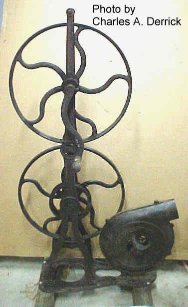
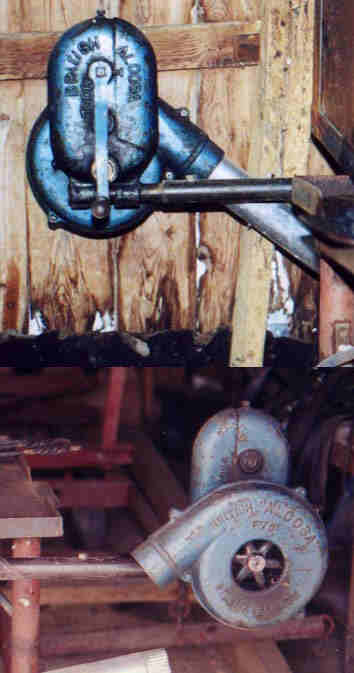
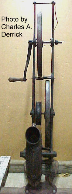 At
left are a couple of photos of a centrifugal blower sent to me by Charles A.
Derrick. In this case the blower is driven by a series of belts and pulleys
rather than the enclosed gearing seen on the blowers above. While this example
looks different than geared blowers, the principle of operation is identical.
At
left are a couple of photos of a centrifugal blower sent to me by Charles A.
Derrick. In this case the blower is driven by a series of belts and pulleys
rather than the enclosed gearing seen on the blowers above. While this example
looks different than geared blowers, the principle of operation is identical.
The pulleys increase or multiply the speed of the impeller as the smith
cranks the handle, in a series of two steps. The first belt fastened from the
top large pulley to the small pulley below it. The small pulley is mounted
permanently to the large lower pulley. A belt fastened around the large lower
pulley to the small pulley on the back of the blower completes this link to
the blower. The speed increase as a result of this stepping of pulleys is
comparable to geared blowers.
Bearings for the pulley axles are Babbitt. There should appear an oil hole
on top of or near each bearing where the axle enters it to, allow oil to flow
into the bearing by gravity.
The belt driven blowers like this one were more common around the mid 19th
century while the geared blowers came into use around the late 19th and early
20th centuries.
The good versus the bad
The good blacksmith blowers all have one thing in common; large impeller
blades. Measured from where they fasten to the impeller hub, to the ends
farthest away from the hub. This length is very important as it is these
extra long paddles that produce the high pressures needed to force air through
the fire, and also to overcome back pressure and resistance caused by the
bends in the delivery piping and tuyere. Most good blowers are approximately
12 inches in diameter. I have had one in the past which was about 9 inches in
diameter which worked just as well but this one had impeller blades of equal
length to the larger blowers, which were simply mounted closer to the center
of the impeller hub, and the blower was geared to spin much faster than a
larger diameter blower to compensate for the smaller diameter.
Squirrel cage blowers such as those found on oil burning or gas burning
boilers and furnaces, heating and air-conditioning systems, or even hair
dryers, will not produce enough pressure to overcome all the resistances in
the blacksmith's fire. For those new smiths who think they will just use a oil
burning furnace blower or hair dryer, I want save you the effort right here.
Don't bother. Instead get a real blower for forge use. Squirrel cage blowers
won't develop enough pressure no matter what diameter they are as the length
of the blades is very short, (measured radial) measured from hub shaft to
outer tip of blades. Again it the long length of the paddles or blades in the
blower which create the higher pressures needed to force air into the
blacksmith's fire. Take this advice from one who has been there. All of the
blowers seen on this page are good blowers. They are worth the effort to find
if the smith wants to build a hand powered forge. I know that many blacksmith
suppliers sell squirrel cage blowers for use on forges. That does not mean
that they have some special brand that works. I used one belonging to a friend
and found out first hand that these little blowers do not perform well enough.
While they do blow some air into the fire, they are not strong enough to make
the fire hot, and the air blast is weak enough that the fire soon packs with
fines as a result of a blast that was too weak to burn the fines away.
Again, save the time and money and buy a real forge blower.
 The
Fire Pot
The
Fire Pot
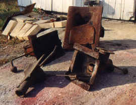
The interior of the firepot is shaped like a bowl and is either round or
square overall shape. Like a bowl, the firepot tapers inwards towards the
bottom, and is 2 to 6 inches deep with 2 - 4 inches being the most practical
depth. The understand why blacksmith's prefer a firepot depth of no more than
2 - 4 inches for heating long bars, see Using the Fire at;
http://www.beautifuliron.com/usingthefire.htm. Built into the bottom of the
firepot is an opening for the air blast to enter the fire, and a tuyere or a
means for attaching one, and a special fixture called a clinker breaker. Photo
at left, the firepot at bottom right is a Centaur Vulcan with a dumping ash
gate. The firepot at top right has a sliding leaf which allows the length of
the fire to be adjusted. Bottom left is a ducks nest for use in building
forges which have no firepot but in which a cast iron tuyere is used and a the
forge hearth is filled with rammed clay to form a depression for the fire. At
top left is the firepot supplied with a ready made forge by Canedy-Otto.
The clinker breaker fits inside the air blast hole in the firepot and
supports the coke from falling through the air blast hole, at the same time,
many clinker breakers are specially designed to direct air flow into the fire
in a very advantageous path for creating very hot fires. Some clinker breakers
are a solid triangular or elliptical shape while others are hollow and slotted
to allow some air blast to actually pass through them as well as around them
into the fire. I found neither style to be better than the other so this is
probably more a matter of opinion as to which is better. As the name 'clinker
breaker' suggests, the clinker breaker is used to loosen clinkers prior to
cleaning the fire. Clinker flows to the bottom of the fire, and by rotating
the handle of the clinker breaker, the oblong shape of the clinker breaker
lifts the clinker and loosens it for easier retrieval from the fire.
Around the outside of the firepot is a large rim which allows the firepot
to be placed upon the forge hearth. The hearth is cut out to allow the firepot
to fit and the firepot rests on its rim inside this cut out area. The Vulcan
style or square firepots were made for use in the old masonry forges that were
very popular in the United States during the early 1900's. Those old forges
had a trough running across the hearth which helped the smith build a high
fire and still place long bars through the heart of the fire. For an example
of one of these old style masonry forges see my Quasdorf Wagon Shop forge page
in Dows Iowa,http://www.beautifuliron.com/cf_QuasdorfDows.htm. The front and rear edges of the
Vulcan style firepot were lower to place them down in this trough in the
masonry forges. For anyone building a simple steel forge without a trough, a
carefully planned set of shims welded to the hearth where the sides of the
firepot will come to rest, will support the firepot at a height that allows
the front and rear edges of the firepot to be level with the hearth. For an
example of how to do this, see the bottom of the page Steel Side draft Forge
at
http://www.beautifuliron.com/cf_MySteel.htm. To create the trough in the
newer style steel forges, several rows of firebrick are placed along the sides
of the firepot.
Ash gates cover the bottom of the tuyere of a firepot. Since fines cinders
fall through the air hole in the bottom of the firepot over time, a means of
removing them periodically from the bottom of the tuyere is needed. The ash
gate allows fines and clinkers to be removed from the bottom of the tuyere,
afterwards the gate is closed so air is forced to flow into the firepot when
the forge is being used.
 The
best firepots are made of heavy cast iron and come supplied with a cast iron
tuyere, clinker breaker, and ash gate. Cast iron resists the intense heat of
the blacksmith's fire without excessive oxidation (rust and scale). The
firepot makes fire tending much simpler and creates an environment in which
much hotter fires are obtained with less effort. The Centaur Vulcan firepot
photo at left (second from left), is a good example of a good blacksmith's
firepot, 4 inches deep, high side rims for use in the old style masonry forges
with troughs, heavy cast iron, a good tuyere and clinker breaker, and choice
of sliding and dumping ash gate (the dumping ash gate being more convenient).
The Centaur Horseshoer's firepot is another good choice, slightly less deep at
about 2-1/2 inches deep, same tuyere and ash gates as used in the Vulcan
firepot, and a round shape and rim. Both available through
Centaur Forge (see my Links page at
http://www.beautifuliron.com/links.htm)
The
best firepots are made of heavy cast iron and come supplied with a cast iron
tuyere, clinker breaker, and ash gate. Cast iron resists the intense heat of
the blacksmith's fire without excessive oxidation (rust and scale). The
firepot makes fire tending much simpler and creates an environment in which
much hotter fires are obtained with less effort. The Centaur Vulcan firepot
photo at left (second from left), is a good example of a good blacksmith's
firepot, 4 inches deep, high side rims for use in the old style masonry forges
with troughs, heavy cast iron, a good tuyere and clinker breaker, and choice
of sliding and dumping ash gate (the dumping ash gate being more convenient).
The Centaur Horseshoer's firepot is another good choice, slightly less deep at
about 2-1/2 inches deep, same tuyere and ash gates as used in the Vulcan
firepot, and a round shape and rim. Both available through
Centaur Forge (see my Links page at
http://www.beautifuliron.com/links.htm)
Good cast iron firepots last a long time. Mine is 20 years old. But they do
have one weakness which must be avoided. Never pour water on a hot firepot.
There is no reason to do this but amateurs often use excessive water on the
fire. When hot firepot comes in contact with water, it will crack or break!
Don't pour water on a hot firepot.
What did blacksmiths do before firepots came into use?
Blacksmiths used sideblast style forges before firepots became available in
the United States. Long after firepots became available, many smiths continued
to build their own sideblast style forges. In some countries today smiths
continue to build sideblast forges. England is a good example. Manufacturers
there continue to make modern sideblast tuyeres available. And I will begin
experimenting with a sideblast style tuyere soon because I suspect that it
allows more welding to be done before the fire clinkers up compared with a
typical firepot. Today most smiths in the U.S. use firepots because they are
convenient, very easy to use compared with other materials in forge building,
and because the sideblast tuyere has not yet made a large appearance on this
side of the ocean.
Blacksmith's built their hearths any way they thought best based on the
types of construction materials available. Everything from a hole in the
ground with a pair of goat skin bladder style bellows, to a large brick
enclosed medieval oven shaped hearth with a flat hearth and a pair of tuyeres
aimed into the side of the fire from the other side of the hearth wall. In
Great Britain side blast forges are still in use made by Vaughns of England
(they apparently bought British Alcosa), large cast iron or fabricated
hearths with a large hood and a rear wall with a cooling water tank and hollow
cast iron tuyere fitted through it and into the fire. These are more
complicated to use compared with an American firepot, but worked very well in
the hands of an expert.
In the 1800's before firepots came into use, the earlier cast iron forge
appliances included the cast iron ducks nest tuyeres. These offered the smith
the ability to quickly maintain a forge hearth made of rammed clay and added
the fast clean out of the tuyere with the addition of the ash gate. Some even
had clinker breaker and focused the direction of the air blast just like
modern firepot tuyeres do now.
The Tuyere
A tuyere is the air blast pipe or plumbing which directs air from the
bellows or blower, into the fire. The tuyere is the air pipe coming directly
in contact with the fire. Good firepots come with a tuyere already assembled
onto them. In the old side blast forges that used bellows, a pipe or pair of
pipes from the bellows directed air into the side of the fire. The pipes were
most likely made of ceramic or stoneware materials used by the local potter,
or were made of clay rammed around some type of core or pattern mold. Ash and
debris in the tuyeres of side blast forges isn't problem since it would simply
be blown back into the fire upon filling the bellows.
New side blast tuyeres in British Alcosa forges are cast iron and bolt onto
the water tank on the back of the forge. A set of gasket seals around the
tuyere through the front and rear of the water tank, makes the connection
water tight and allows the water in the tank to circulate through the tuyere
to cool it. The air supply pipe fits into the open rear of the tuyere.
The tuyere on the firepot is bolted to the bottom of the firepot. It
delivers air to the bottom of the fire and has sump in the bottom to catch
cinders that fall through the clinker breaker and keep them out of the way of
the air blast. A gate or valve built onto the bottom of the sump allows the
sump to be emptied periodically and is then closed to block air blast from
escaping through the opening. There are two styles of ash gates. One is a
sliding ash gate, held on with a single bolt or screw. By rotating the sliding
gate, the ash falls out the bottom of the sump. Friction keeps the sliding ash
gate in place. The other type of ash gate is a dumping ash gate. The dump gate
pivots on a single bolt and is held closed by a counter weight built onto it
opposite the gate valve. The dumping ash gate is far more convenient and
comfortable to use. but both work well.
In the area just beneath the flange mount of the firepot (just below the
firepot) a hole is drilled through both sides of the tuyere for the clinker
breaker pivot rod. A clinker breaker is then fitted in the middle of the air
blast hole between the tuyere and firepot, and the pivot rod is inserted
through the it and the drilled holes in the tuyere. The clinker breaker is
secured to the pivot rod with a bolt or screw and since it is exposed to
intense heat, the screw will seize to the rod and cannot be removed easily
later on. Forge builders must plan on this since moving the firepot to a new
forge may be hindered by awkward placement of the pivot rod. The short pivot
rods supplied with these firepots is a good length to work with.
Updated
September 29, 2019.
This page is still under construction and more to be added.
The author can be emailed at address in picture below:

Page created April 2000.

