Camelback Drills
[Home]
[Back to Ye Old Drill]
[Camelback Drills] [Morse
Taper] [Standard
No. 2 Chuck] [Westcott's
Little Giant Chuck] [Jacobs
Chucks] [The Post
Drill] [Restoring
Canedy-Otto No. 16]
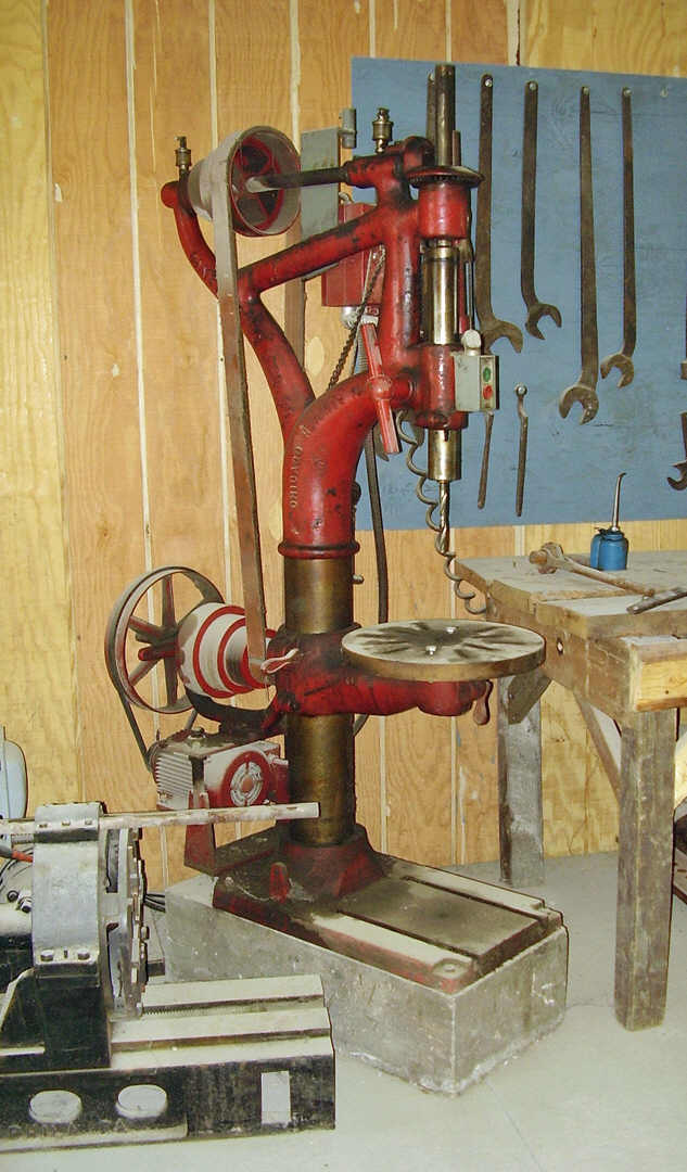
 The
name 'camelback' refers to the peculiar humped cast iron center frame to which the
main shaft and pulleys and gearing were built up. The camelback has the most
distinctive appearance of any drill press ever manufactured. This is an antique
style of drill press manufactured around the end of the 19th century and well into
the first half of the 20th century, and were still being manufactured until the
1970s. Today these antique style drills are often found for sale when older
welding and blacksmith shops and farms go to auction. Some people today are
skeptical of these old drills - often mistakenly believing that these old
drills don't work simply because they don't look like modern drill presses. But to
those of us who use them, these old style drills are very practical and highly
desirable for nearly every drilling job. Camelback drills turn much slower than
modern drill presses, and this slower drill speed greatly extends drill bit life
by reducing the heat build-up in the drill bit. And camelback drills operate much
more quietly and smoothly than modern drill presses - thus reducing operator
fatigue. These old drills were built solid to last a lifetime and this they
certainly did, many camelbacks outlived their original owners and continue to
serve multiple generations of metalworkers today!
The
name 'camelback' refers to the peculiar humped cast iron center frame to which the
main shaft and pulleys and gearing were built up. The camelback has the most
distinctive appearance of any drill press ever manufactured. This is an antique
style of drill press manufactured around the end of the 19th century and well into
the first half of the 20th century, and were still being manufactured until the
1970s. Today these antique style drills are often found for sale when older
welding and blacksmith shops and farms go to auction. Some people today are
skeptical of these old drills - often mistakenly believing that these old
drills don't work simply because they don't look like modern drill presses. But to
those of us who use them, these old style drills are very practical and highly
desirable for nearly every drilling job. Camelback drills turn much slower than
modern drill presses, and this slower drill speed greatly extends drill bit life
by reducing the heat build-up in the drill bit. And camelback drills operate much
more quietly and smoothly than modern drill presses - thus reducing operator
fatigue. These old drills were built solid to last a lifetime and this they
certainly did, many camelbacks outlived their original owners and continue to
serve multiple generations of metalworkers today!
This page under construction
September 16, 2019
Strong, quiet, smooth running, long life.
These features were common among the larger camelbacks with drill socket sizes
of 2MT and larger.
The drill turns forcefully and will easily bore the largest holes in steel.
Camelback drills are substantially heavier than modern pipe mounted drill presses
and the greater weight offers a much more steady feel with less vibration and
lower noise level during use compared with a modern drill of similar size. Heavy
cast iron parts last a long time, after all, the drills are still working after as
much as a century of service.
Camelbacks manufactured during the later part of the era often have an
auto-feed gear that allows the drill to bore holes by itself (the user must
monitor the operation and shut off the auto-feed at the end of the process). The
drill can be used with flat belts on a line shaft or mounted with a modern
electric motor. A sash weight or counterweight hidden inside the central frame
supports the weight of the quill and spindle. Using a counterweight rather than a
spring to support the weight of the quill is an advantage over the modern drill
press because the quill will remain stationary rather than suddenly jumping back
up into the drill frame when the user disengages the feed lever.
Taper shank sockets and taper tooling continue to be the standard today.
MT taper shank (morse taper shank) drills, reamers, and chuck arbors are available
from most large machinery suppliers in the U.S. Modern drilling machines continue
to use MT shank tooling so we can reasonably expect MT tooling to be widely
available for many years to come. Taper shank tooling is easy to use and the
reader can learn more about this tooling by visiting my webpage here:
http://www.beautifuliron.com/mttaper.htm
Typical sizes of drill sockets available. Most camelbacks have # 2MT and
# 3MT taper sockets. These two taper sizes are the most numerous as they are used
for the majority of drilling applications between 1/8" to 1-1/8" that would have
been typical in blacksmith's shops, machine shops, and other small contractors
businesses. Larger drills were also available and drills with # 4MT - 6MT and
these larger machines were employed in the large manufacturing shops. The larger
drills were of course less numerous but can still be found, although it is much
tougher to get the owner to part with the larger camelbacks as there are no
inexpensive modern replacements.
In addition to the sizes discussed above, numerous 1MT socket table-top drill
presses were also available. The small drills were cheaply made just as modern
small drill presses are cheaply made today, and consequently few survive, and none
of the small table-top models are worth the effort to repair once they break.

 One
man's castaway is another's treasure. While the Camelback has been literally
sent to the antique scrap heap by most modern service and industrial businesses,
it still offers a tremendous serviceability to the modern blacksmith and
ornamental iron or fabrication shop. Ugly and strange as many people would
probably find the appearance of these old drills, these machines are wonderful to
work with. So why then do most 'modern' businesses discard these drills?
One
man's castaway is another's treasure. While the Camelback has been literally
sent to the antique scrap heap by most modern service and industrial businesses,
it still offers a tremendous serviceability to the modern blacksmith and
ornamental iron or fabrication shop. Ugly and strange as many people would
probably find the appearance of these old drills, these machines are wonderful to
work with. So why then do most 'modern' businesses discard these drills?
Possible reasons that most "modern" businesses don't want camelback drills
- Most businesses today want a drill that turns fast. The camelback turns very
slow compared with a modern pipe-mounted drill press. The typical business owner
today knows little or nothing about drills and recommended drill bit speeds.
- Camelback drills do not meet OSHA standards due to open belt and gearing
design. Typically a business prefers to purchase only machinery that is ready
for use immediately after purchase, with no additional work such as building the
guards that are needed to bring this drill up to OSHA standards. This is
probably the most legitimate reason for purchasing a modern style drill rather
than a camelback.
- Businesses today want a drill that is light and easy to move. Why I don't
know. Maybe they plan to pack up and move like nomadic camel herders or
something. The drill is meant to be set up in one place and not moved. OSHA
requires that machinery be bolted to the floor. It is hard to move when bolted
down anyway. Again this harkens back to the lack of understanding by management
concerning how machinery is actually used.
- These drills require regular maintenance on a daily and weekly basis. The
camelback must be oiled and wiped clean daily or suffers excessive wear or
deterioration of important metal surfaces. By comparison modern pipe-mounted
drill presses have sealed bearings that never receive lubrication during the
life of the drill, and few lubrication points that require oil, such as feed
shaft bearings and table clamp joints and threads. All modern shops pay lip
service to equipment maintenance. They don't actually take care of the tools
except to put them away after use. A modern pipe mounted drill is quickly
discarded and replaced when it wears out or breaks down a few years later. The
camelback would require more maintenance than modern workers accomplish and
business managers are aware of this so it is a legitimate reason for not
purchasing a camelback.
- Camelback drills are not supported with parts and service. This means the
owner must make all parts and repair the drill themselves. A good reason for
businesses today to not purchase a camelback. Machine shops on the other hand
don't find this to be a disadvantage. This reason for not purchasing only
applies to shops that do not perform their own tool maintenance.
 Counterpoints
why a camelback drill is desirable in a blacksmith's shop
Counterpoints
why a camelback drill is desirable in a blacksmith's shop
- Camelbacks turn slowly. This is a great advantage! The camelback will drill
at the recommended speed, or slower, for a given size of drill bit. The slower
speeds will not burn drill bits. The camelback turns with greater force than
modern drill presses due to the effects of gear and pulley size ratios. The
camelback will drill large holes faster than a modern high-speed drill press.
- Guards and screens can be made easily to bring these drills up to OSHA
standards. Obviously fabricating guards is not a advantage for buying a drill.
But the value of the slower speeds makes obtaining a camelback worthwhile and
well made guards dramatically improve the resale price of a drill that is in
good condition. Lack of guards causes prices of these drills to remain low as
modern businesses do not bid up prices at sales for a drill that run them afoul
of OSHA. If the owner works alone then making guards isn't required. But if the
drill is to be used by others, then guards will be required. Look farther down
this page for suggestions on belt guards.
- These drills are heavy. This is a great advantage! Heavy weight absorbs
vibration and noise, and makes the camelback more comfortable to use. An
excellent advantage.
- Machinery from the bygone era of industrialization required regular and
daily care- oiling and wiping. The required maintenance dissuades modern
businesses from purchasing these drills. Consequently reducing the price bidding
at sales. The maintenance is easy and quick. A drop of oil in each of the oil
holes, a squirt in each bearing cup. Wipe once with a rag. Do this once every
couple weeks if the drill is not in use. When compared with the difference in
drilling time for holes larger than 1/2", camelback will complete the job in
less than half the time. A set of 4 holes 1-1/8" may take an hour with a
camelback. How long would it take with a modern drill that lacks the power to
turn the bit in large holes? How many hours would be spent sharpening bits that
burned up because the modern drill turned to fast? A great trade off- we spend a
few minutes a day caring for our equipment, and reduce drilling time by roughly
half of the time that would have been required by a modern drill press.
- Camelbacks are not supported by parts and service. The only advantage here
is that prices of camelbacks are held down by lack of sales support. If the
drill is broken or worn, it will need parts and repairs that can only be made by
the user. If the drill is broken, then bid price is lower.

 Still
a popular design. These are one of the most sought after drills on the market
for ornamental iron shops, blacksmiths, small steel fabricators, mechanics,
farmers, and hobby smiths. And when in good serviceable condition, these drills
often bring substantially higher bids at auctions and private sales than the
typical modern style drill press. This is because these drills are built for
heavier work than their typical modern counterparts, are comfortable and
convenient to use, and turn slowly enough to reduce the breakage or damage to
expensive bits.
Still
a popular design. These are one of the most sought after drills on the market
for ornamental iron shops, blacksmiths, small steel fabricators, mechanics,
farmers, and hobby smiths. And when in good serviceable condition, these drills
often bring substantially higher bids at auctions and private sales than the
typical modern style drill press. This is because these drills are built for
heavier work than their typical modern counterparts, are comfortable and
convenient to use, and turn slowly enough to reduce the breakage or damage to
expensive bits.
Let me give you an idea of how popular these drills are today. At almost every
sale that I have attended when a camelback drill was being sold, the bids start
high and go up fast, often starting at double the price of a new drill press.
These drills often were often among the top priced items of the sale. Even drills
that are not complete or that are in poor repair, will receive high price offers.
A good camelback drill is popular enough that once found, a prospective buyer
must move quickly to close the sale or risk seeing another buyer take it home
instead, often resorting to secrecy to avoid alerting other buyers to the
discovery of a really good drill that has been offered for sale. I delayed
publishing this page to my website for this reason; to avoid alerting readers in
my local area to the fact that I found a really nice drill for sale at a lower
price than a lesser quality drill would have brought at auction.
Where to find these drills. Machine shop auctions, farm auctions,
blacksmith and welding shop auctions. Machine and tool auctions. Used machine
distributors and dealers. Look on the internet for machinery sales. Sometimes they
can be found at antique and steam engine shows and swap meets. I found a really
nice drill that was over 130 years old and still in excellent condition at an
antique tractor swap meet. Occasionally machine shops sell excess equipment. One
of my drills came from a machine shop that bought excess equipment as a sort of
package deal to get another machine that they wanted. They ended up selling me one
of those drills. Camelback drills are tough to find. Their owners seldom are
willing to part with one of them. But once the drill becomes available, be
prepared to spend several hundred dollars at least. More if the drill is in full
working condition.
How they are used.
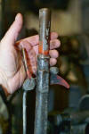

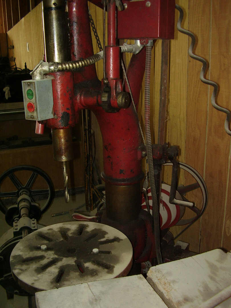
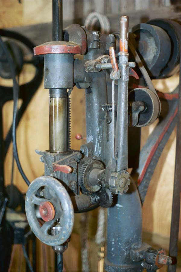
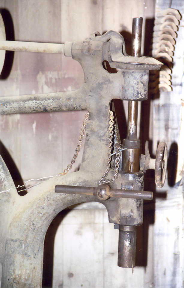
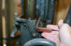
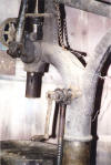
 Drill
feeds and quills. The basic and most common style feed levers were a single
long handle with a clutch style lever handle - to adjust position on the notched
feed shaft. The authors Excelsior drill (pictured at right) is an example of a
long feed handle with clutch lever grip. The clutch lever on the feed handle,
pulls the pawl out of the notches in the feed shaft wheel (to which the handle
rotates around). When the clutch is squeezed, the feed handle can be positioned
over a different notch in the feed shaft wheel, and releasing the clutch allows
the pawl to re-engage in the notches of the feed shaft wheel. This action allows
the camelback feed handle to be positioned at any point or height that the user
desires. An additional feed handle mounted to the opposite end of the feed shaft
(on the opposite right side of the drill) can also be used to move the drill quill
up and down -while the user is squeezing the clutch thus allowing the feed shaft
to rotate freely inside the long feed handle. This style of feed handle with its
pawl lever, is much more comfortable to work with compared with the 3-lever handle
of a typical modern drill press . The camelback drill feed handle is longer than
the typical 3-lever feed handle on the modern drill press, and the longer length
allows the mechanic to apply the same force to the drill bit with less effort
because of the extra leverage of the handle. Visible in the photos (photos near
right and middle right), the clutch pawl and notched feed shaft wheel wheel are
clearly visible. Look closely in the first photo - the clutch pawl can be seen to
be engaged in a notch in the feed shaft wheel. A think clutch link rod is seen
exposed below the quill feed handle, and this link rod is connected inside the
quill feed handle to the pawl on the end of the feed handle. Also visible in the
photos (photos near right and middle right), the auto feed drive gears can be seen
mounted underneath and behind the feed shaft gear.
Drill
feeds and quills. The basic and most common style feed levers were a single
long handle with a clutch style lever handle - to adjust position on the notched
feed shaft. The authors Excelsior drill (pictured at right) is an example of a
long feed handle with clutch lever grip. The clutch lever on the feed handle,
pulls the pawl out of the notches in the feed shaft wheel (to which the handle
rotates around). When the clutch is squeezed, the feed handle can be positioned
over a different notch in the feed shaft wheel, and releasing the clutch allows
the pawl to re-engage in the notches of the feed shaft wheel. This action allows
the camelback feed handle to be positioned at any point or height that the user
desires. An additional feed handle mounted to the opposite end of the feed shaft
(on the opposite right side of the drill) can also be used to move the drill quill
up and down -while the user is squeezing the clutch thus allowing the feed shaft
to rotate freely inside the long feed handle. This style of feed handle with its
pawl lever, is much more comfortable to work with compared with the 3-lever handle
of a typical modern drill press . The camelback drill feed handle is longer than
the typical 3-lever feed handle on the modern drill press, and the longer length
allows the mechanic to apply the same force to the drill bit with less effort
because of the extra leverage of the handle. Visible in the photos (photos near
right and middle right), the clutch pawl and notched feed shaft wheel wheel are
clearly visible. Look closely in the first photo - the clutch pawl can be seen to
be engaged in a notch in the feed shaft wheel. A think clutch link rod is seen
exposed below the quill feed handle, and this link rod is connected inside the
quill feed handle to the pawl on the end of the feed handle. Also visible in the
photos (photos near right and middle right), the auto feed drive gears can be seen
mounted underneath and behind the feed shaft gear.
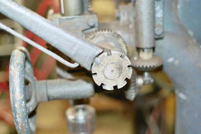
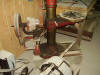
 Another
style of feed lever. Here is a close up view (photo at right) of the sliding
quill support arm and quill feed lever on the authors Cincinnati-Bickford. The
feed lever is simple plain round rod with flat side machined into it. This feed
lever is adjustable by loosening the jam screw and sliding the feed handle to the
desired position, and then re-tightening the jam screw against it again. The jam
screw is threaded into the end of the feed shaft. The jam screw has a 'T' handle
welded to it so that the mechanic can quickly loosen and tighten the feed lever
without using a wrench. The feed lever is seen here set up with equal length on
both sides of the feed shaft.
Another
style of feed lever. Here is a close up view (photo at right) of the sliding
quill support arm and quill feed lever on the authors Cincinnati-Bickford. The
feed lever is simple plain round rod with flat side machined into it. This feed
lever is adjustable by loosening the jam screw and sliding the feed handle to the
desired position, and then re-tightening the jam screw against it again. The jam
screw is threaded into the end of the feed shaft. The jam screw has a 'T' handle
welded to it so that the mechanic can quickly loosen and tighten the feed lever
without using a wrench. The feed lever is seen here set up with equal length on
both sides of the feed shaft.

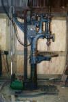
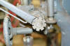
 Power
auto-feed. Some camelbacks also offered a powered auto-feed function that used
a belt to transmit power to turn auto feed screw that in turn, forced the feed
shaft to rotate downward forcing the drill into the work. This was a throwback to
the earlier drills that used a series of ratchets and levers, like those found on
the auto-feed mechanisms of hand cranked post drills. At right again is the
authors Excelsior drill for this example. A small jack-shaft style stepped pulley
is mounted on the drill drive shaft above the power take-off for the auto feed.
Auto feed speeds can be set by moving the belt onto different steps of the
step-pulley.
Power
auto-feed. Some camelbacks also offered a powered auto-feed function that used
a belt to transmit power to turn auto feed screw that in turn, forced the feed
shaft to rotate downward forcing the drill into the work. This was a throwback to
the earlier drills that used a series of ratchets and levers, like those found on
the auto-feed mechanisms of hand cranked post drills. At right again is the
authors Excelsior drill for this example. A small jack-shaft style stepped pulley
is mounted on the drill drive shaft above the power take-off for the auto feed.
Auto feed speeds can be set by moving the belt onto different steps of the
step-pulley.
NOTE: the feed handle must be stowed in the upright position to use auto feed.
The on the back of the clutch lever of the feed handle there is a spur. The spur
protrudes through the slot of the feed handle and extends a several inches through
the opposite side of the feed handle. The spur has a curved taper shape and a
notch close to the widest part of the spur nearest the feed handle. The curved
tapered shape allows the clutch lever to be squeezed underneath a peg mounted to
the drill frame. When the feed handle is stowed in the 'up' position, the spur on
the clutch lever is squeezed under the peg and the notch in the spur catches under
the peg. With the feed clutch handle squeezed, the pawl is disengaged from the
feed shaft and the feed shaft can rotate freely. And with the feed handle thus
stowed, the quill can be moved freely up or down as needed or instead, the auto
feed can now be engaged.

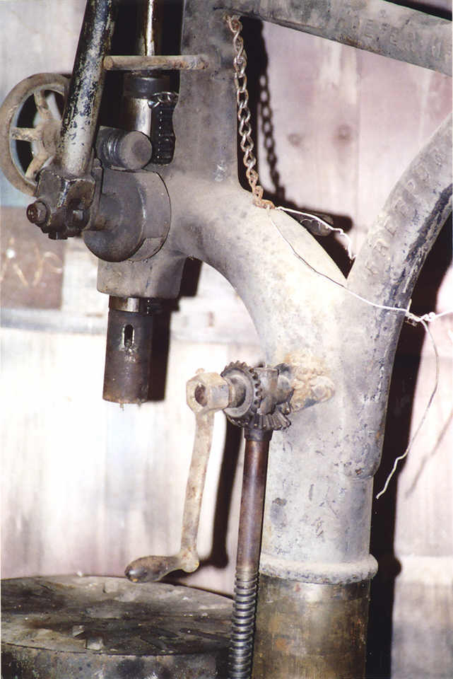
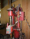
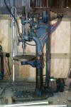
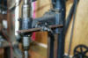
 The
small belt turns a shaft that is mounted parallel to the drill drive shaft.
Through a worm and right angle gear this shaft turns a vertical shaft, and the
vertical shaft turns a second horizontal worm shaft.. Normally the worm gear and
drill feed shaft gears are not engaged. Since the auto feed drive belt is
constantly turning with the drill drive, the worm drive must be disconnected from
the feed shaft when not needed. To engage the auto-feed, the second horizontal
worm is lifted into position with a lever on the front of the drill. This can be
done with the drill running. The worm turns slowly so the engagement lever
(painted red in picture at right) is lifted and held up until the worm engages the
teeth of the feed shaft gear and the lever seats in its detent. To disengage, the
release lever is pulled down and the engaging lever unseats and falls.
The
small belt turns a shaft that is mounted parallel to the drill drive shaft.
Through a worm and right angle gear this shaft turns a vertical shaft, and the
vertical shaft turns a second horizontal worm shaft.. Normally the worm gear and
drill feed shaft gears are not engaged. Since the auto feed drive belt is
constantly turning with the drill drive, the worm drive must be disconnected from
the feed shaft when not needed. To engage the auto-feed, the second horizontal
worm is lifted into position with a lever on the front of the drill. This can be
done with the drill running. The worm turns slowly so the engagement lever
(painted red in picture at right) is lifted and held up until the worm engages the
teeth of the feed shaft gear and the lever seats in its detent. To disengage, the
release lever is pulled down and the engaging lever unseats and falls.

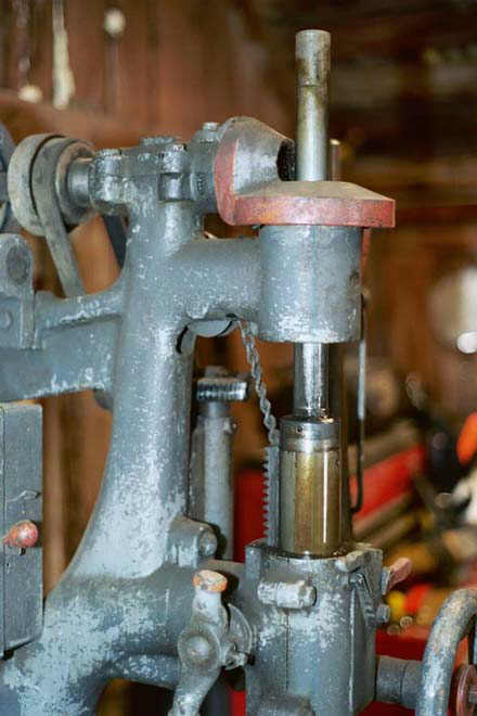
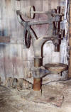
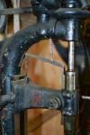 Sash
weights support the weight of quill and spindle. The quills on camelback
drills are usually supported with a chain and sash weight hidden inside the
central frame of the machine. A couple of pulleys allow the chain support to move
freely within the drill as the drill quill moves up and down. One of these pulleys
can be seen above the quill at the point where the chain support comes out of the
central frame. Both examples at right show the chain exiting the drill frame above
the quill and fastening to the top of the drill quill. The picture (near right)
shows the authors Cincinnati Bickford drill with a sliding quill support arm. In
this case the chain fastens to an arm that in turn fastens to the top of the
quill. The opposite end of the arm is fastened by way of a chain, to the rear of
the sliding quill support. The arm moves up and down along with the quill support
and in this way, allows the counterweight to always apply lifting force nearly
straight up, at any height that the quill support arm is raised to.
Sash
weights support the weight of quill and spindle. The quills on camelback
drills are usually supported with a chain and sash weight hidden inside the
central frame of the machine. A couple of pulleys allow the chain support to move
freely within the drill as the drill quill moves up and down. One of these pulleys
can be seen above the quill at the point where the chain support comes out of the
central frame. Both examples at right show the chain exiting the drill frame above
the quill and fastening to the top of the drill quill. The picture (near right)
shows the authors Cincinnati Bickford drill with a sliding quill support arm. In
this case the chain fastens to an arm that in turn fastens to the top of the
quill. The opposite end of the arm is fastened by way of a chain, to the rear of
the sliding quill support. The arm moves up and down along with the quill support
and in this way, allows the counterweight to always apply lifting force nearly
straight up, at any height that the quill support arm is raised to.
The photo (above far right) shows the authors Excelsior and here the chain
fastens directly to the top of the quill.
Sash weights and chain supports are quite different from modern drill presses
that use a spring return fastened to the opposite end of the feed lever shaft from
the feed lever. With a sash weight or counterweight there is no tendency for a
camelback quill to quickly snap back upward suddenly if the user lets go of the
feed handle. Instead the quill will often remain stationary until the user lifts
the quill upward again. This is handy in that the user can place the drill close
to the work to make adjustments without need for holding the feed lever down
against any spring pressure. The quill will simply stay in place at what ever
height the user most recently moved the quill to. However a ratcheting style feed
handle will rotate downward under its own weight unless stowed in the upright
position.
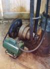
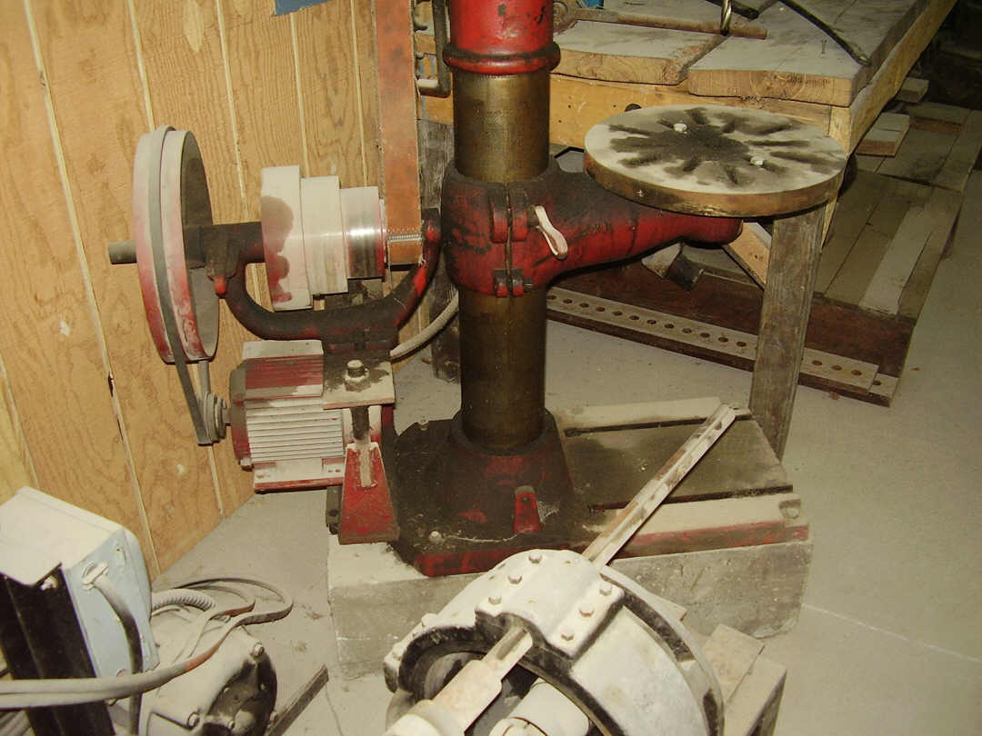
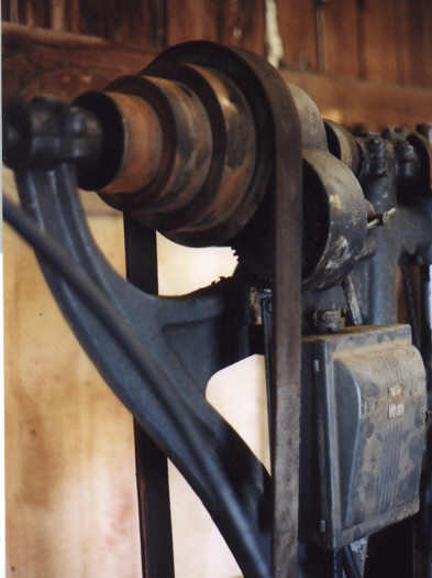
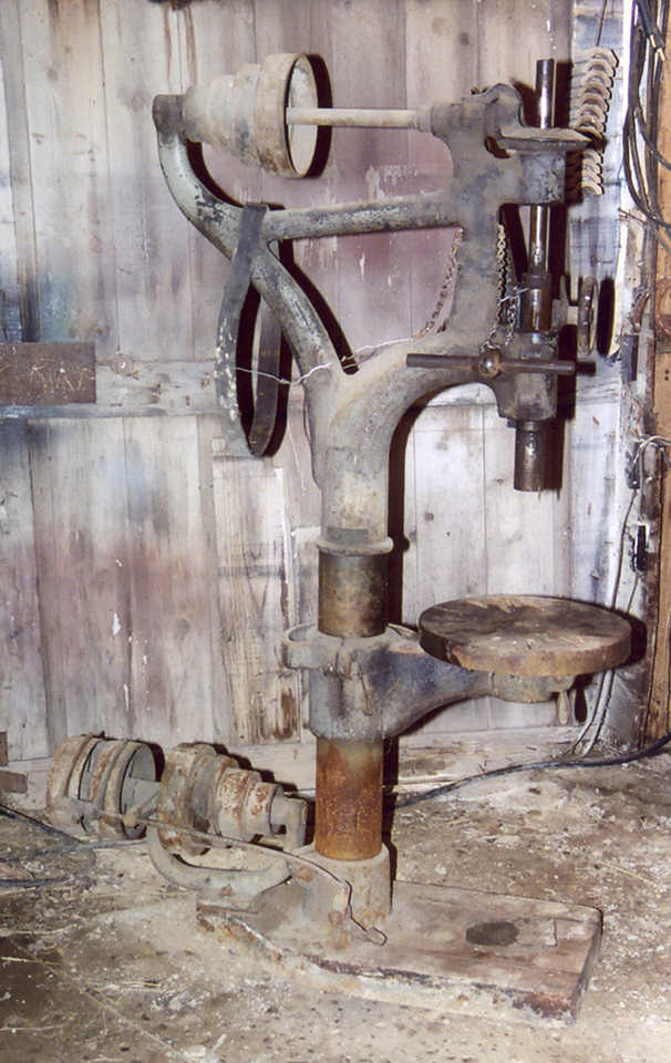
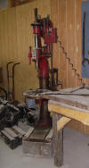
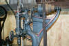
 Jacks
shafts and line shafts. Looking at the pictures here at right of my Excelsior
20-inch drill, this is a fairly typical example of a flat belt style drive with a
jack shaft. The stepped pulleys allow three different combinations or speed
changes. One set of step pulleys mounted directly on the drill's drive shaft at
the top of the machine and the other mounted to the jack shaft mounted lower down
on the machine, in this case the jack shaft mounted at the foot or base of the
drill. Most shops during the turn of the century (1800's-1900's) used a line shaft
driven by either a steam engine, internal combustion engine, or sometimes an
electric motor, to supply power or motion to all of the tools connected to it.
Tools and machines were most often connected to the line shaft by a series of
belts and pulleys. The jack shaft is a transmission or power take-off shaft that
transfers power from an existing source such as the existing motor or line shaft
pulleys.
Jacks
shafts and line shafts. Looking at the pictures here at right of my Excelsior
20-inch drill, this is a fairly typical example of a flat belt style drive with a
jack shaft. The stepped pulleys allow three different combinations or speed
changes. One set of step pulleys mounted directly on the drill's drive shaft at
the top of the machine and the other mounted to the jack shaft mounted lower down
on the machine, in this case the jack shaft mounted at the foot or base of the
drill. Most shops during the turn of the century (1800's-1900's) used a line shaft
driven by either a steam engine, internal combustion engine, or sometimes an
electric motor, to supply power or motion to all of the tools connected to it.
Tools and machines were most often connected to the line shaft by a series of
belts and pulleys. The jack shaft is a transmission or power take-off shaft that
transfers power from an existing source such as the existing motor or line shaft
pulleys.
Jack shafts in use. In addition to the step pulley mounted on the jack
shaft, there were also a pair of pulleys mounted to the end of the jack shaft. One
of the pair being fixed permanently to the jack shaft so that turning it would
force the jack shaft to turn, and the other pulley mounted as a 'free' pulley that
could spin freely without causing the jacks shaft to turn. The pair of pulleys
were connected to the line shaft through a power belt. A shifting fork was mounted
beside the pair of pulleys on the jack shaft and the power belt slipped between
the tines of this fork. By use of a spring loaded pedal or other device, the
shifting fork could be moved and used to force the power belt off the free pulley,
onto the fixed pulley. Normally the shifting fork would be spring-loaded to hold
the power belt on the free pulley allowing the drill to remain still until, the
drill operator moved the shifting pedal or lever forcing the belt onto the fixed
pulley causing the drill to rotate.
Most of us today don't use a shifting fork on our jack shafts. Instead the
motor drive belt is placed on the fixed pulley. We simply flip a switch to start
the motor. Step pulleys are still used for speed changes. The motor is turned off
and the belts are moved to the appropriate step pulley.
Changing speeds with step pulleys. To change speeds, shut off drill and
disconnect it from its electrical power source. Since the belt is already tight,
we need some slack to shift from one pulley to the other. So after deciding which
direction the belt must move (is the belt to be moved to the rear or to the
front?) the belt will first be moved off the larger of the pulley steps that is it
on. It should be noted that the top and bottom pulley are mounted in opposite
directions. The smaller end of the one pulley facing the opposite direction of its
mate. Take a look at the photo at the top of this page to see the directions that
each of the pulleys placed. The pulley step on one shaft will be large while the
corresponding pulley step on the opposite shaft will be smaller. Walk the flat
belt off the larger to the smaller pulley. Then at the other end of the belt, walk
the belt over the larger pulley and turn the pulley as needed to allow the belt to
climb onto the pulley.
Maintaining a Camelback drill.
Oil everything! Bearing oil cups are easy to access. Every shaft that
turns or moves or slides, requires oil. If it moves inside of, next to, or against
another part, it needs lubrication. If you can't find the lubrication holes than
it is possible that they have plugged with dirt or have been painted over. Find
the lubrication holes and clean them out. Fill them with oil at least once a week
and all oil cups must be filled daily when the drill is in use. Oil cups should be
plugged with felt to prevent dirt and abrasives from entering the oil holes and
contaminating bearings. The felt acts as a screen to prevent dirt and debris from
entering the bearings, and oil is simply added on top of the felt and allowed to
seep through slowly to the bearings. The oil cups are normally found on top of the
bearing caps of large shafts such as the jack shaft bearings and the upper drill
drive shaft that runs at the top of the drill. Old drills used babbitt bearings
for all large shafts. All babbitt bearings require daily oiling. Again, oil
everything! If it is iron or steel and it moves against something else, oil it.
Some parts have no holes for oiling, such as the table height jack screw and table
slide surfaces. In this case the oil is simply applied to the joints of the jack
screw and the jack screw threads. Oil is wiped onto the sliding surfaces of the
frame post where the table slides up and down on the outer surface.
Motors. Most of the time we find these drills with antique motors still
installed. The antique motors seldom are worth saving. Most are junk. Be prepared
to replace the motor before putting the drill into service. Big drills don't
necessarily need big motors. These drills turn much slower than modern drill
presses. Consequently the slower speeds mean that the motor on these drills have
more leverage or torque available. I used a 1-horsepower motor on a drill with a
3MT socket. So far this size has worked fine. If the motor should prove
underpowered in the future, I might change to 1-1/2 horsepower. So plan on
1-horsepower for a 2MT socket drill and either a 1 or a 1-1/2 horsepower motor for
a drill with a 3MT socket.
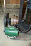
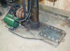
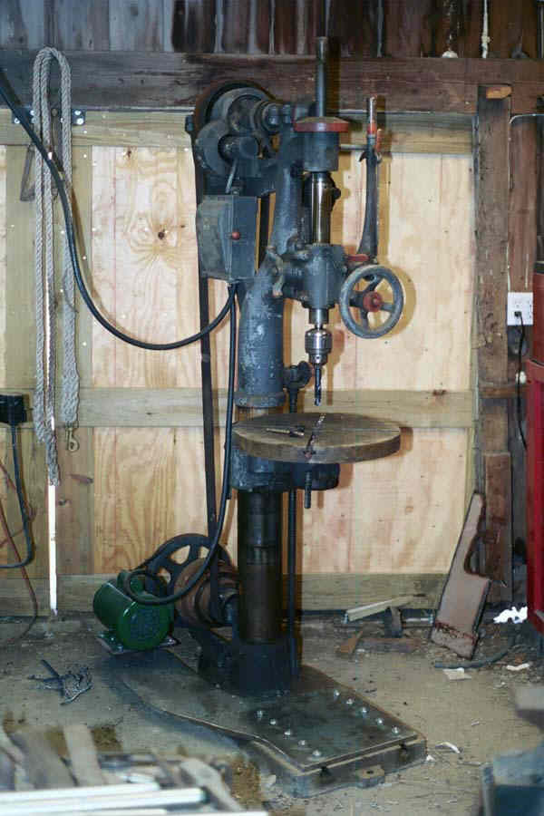
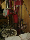
 Installing
a electric motor on a line shaft driven drill. Mounting electric motors on
camelbacks is difficult at best. The simplest way is to bolt a heavy steel plate
to the top of the cast iron base of the drill, and mount the motor to the plate.
At right is my Excelsior with a 5/8ths-inch steel plate cut to wrap around the
center frame of the drill and support a motor near floor level.
Installing
a electric motor on a line shaft driven drill. Mounting electric motors on
camelbacks is difficult at best. The simplest way is to bolt a heavy steel plate
to the top of the cast iron base of the drill, and mount the motor to the plate.
At right is my Excelsior with a 5/8ths-inch steel plate cut to wrap around the
center frame of the drill and support a motor near floor level.
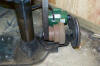
The T-slots in the base plate make excellent fastening points for installing
bolts. The base is cast iron and is not nearly so strong as steel, so use plenty
of bolts and plan to tighten them only a small amount to avoid breaking the
T-slots in the base. I used ten 5/8ths inch carriage bolts with the heads ground
slightly flat on two sides to allow them to pass through the T-slots in the base
of the drill.
The plate is cut to rest across the whole of the drill base. Spreading
the placement of the bolts over the entire area of the T-slots, so that the force
of tightening the bolts is spread evenly across the area of the mounting slots.
The plate curves around the center frame of the drill and extends to the back of
the drill, almost to the fixed pulley or (in this case) the v-belt pulley. Keep in
mind that the motor must be located far enough away from the jack shaft so that it
doesn't interfere with the flat belt that drives the drill. The plate should be
balanced well enough that it can rest on base of the drill without falling off.
The motor can be mounted to either the end of the mounting plate, or as
used on my drill, a small platform can be welded to the mount plate and the motor
mounted to the platform. Slots are cut in the back of the mounting plate or motor
platform for adjusting the motor.
Repairing the Camelback drill.
Repairing a camelback drill requires expert ability in a variety of skills.
Machining gears or shafts, forging iron and steel parts, welding critical machined
cast iron parts, setting up and pouring new babbitt bearings, and expert
mechanical skills in inspection and repair of machinery. If you do not posses
expert skills in each type of repair then do not attempt them until you have been
trained. A botched repair can destroy a part or greatly reduce its value.
Welding cast iron parts. Cast iron parts can be welded using the proper
cast iron welding techniques and correct electrode. Cast iron welding requires a
great amount of peening and grinding/cleaning between each pass with the welder.
If you don't understand why cast iron welding requires peening then don't attempt
it until you learn why it is necessary. Gouge and chamfer all weld area deeply.
Cast iron type electrode has very poor penetration and the only effective way to
regain the full strength of the part at the break, is to begin the weld as close
to the center of the break as possible. Never allow the use of standard welding
electrodes for steel, as any electrodes for steel will react with the cast iron
and cause a very hard and brittle weldment and will eventually fail or prevent any
other type of machining such as re-drilling holes. Use only machinable nickel type
electrodes. The nickel rod does not weld over flux that remains from the previous
pass, and neither does it penetrate small narrow gaps between pieces. All flux and
narrow gaps must be gouged and down to bare metal and wide rounded bottoms of the
chamfers. Expect to see more than half of each weld bead removed during cleaning
and gouging between each pass. If this is too expensive for you then you don't
posses the skill to do the work anyway. Cast iron welding is not for amateurs.
Repairing botched welds. If a drill is acquired with a botched weld from
a previous repair job, there are still ways to undo the damage and give a good
repair. For example a drill is acquired with a broken bracket that the previous
owner attempted to weld with standard steel type electrode. All of the effected
area that was filled in with the standard type of electrode for welding steel,
will have been destroyed and cannot be saved. The entire failed weld will need to
be cut out with a grinder.
A steel patch can be used to fill in any gaps between the parts to be welded.
Steel can be welded to cast iron using the same welding techniques and welding
electrode as for cast iron welding. Keeping in mind that the cast iron side of the
repair still suffers the same stresses from welding despite the presence of the
steel patch. And due to the presence of cast iron in the repair, only machinable
nickel welding rod can be used. The same rules still apply for gouging and
chamfering the effected repair area, and peening and grinding the weld between
each pass.
The cast iron electrodes are made of an alloy containing nickel. This alloy is
desirable because it does not absorb large amounts of carbon from the weld area
and therefore does not harden after welding. When the weld is completed, both the
fill material and parent material are soft enough to be drilled and machined as
though made of soft cast iron.
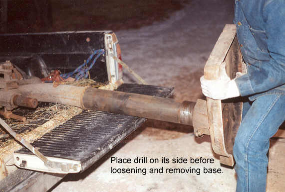
Removing base and table support.
 The
camelback drill stands upright in a support clamp specially cast and machined in
the base. The central post of the drill is hollow and contains the sash weight
that acts as a counter-weight to support the weight of the drill spindle and other
parts. The sash weight is hung inside the central post with a chain that extends
up through the top curve or arch that supports the drill spindle and feed
assembly. With one end of the chain fastened to the top of the sash weight, and
the other end of the chain hung over a pulley mounted in a slot or hole in the
curve of the post and finally connected to the top of the drill feed quill.
The
camelback drill stands upright in a support clamp specially cast and machined in
the base. The central post of the drill is hollow and contains the sash weight
that acts as a counter-weight to support the weight of the drill spindle and other
parts. The sash weight is hung inside the central post with a chain that extends
up through the top curve or arch that supports the drill spindle and feed
assembly. With one end of the chain fastened to the top of the sash weight, and
the other end of the chain hung over a pulley mounted in a slot or hole in the
curve of the post and finally connected to the top of the drill feed quill.
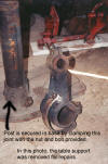
To gain access to the sash weight, or to remove other large parts such as the
table support bracket, the base plate must first be removed from the bottom of the
drill. Place the drill on its side, on a suitable support such as a low table or
horses or the back of a truck. Loosen the clamp bolt that secures the base around
the bottom of the post. Apply penetrating oil and work the base from side to side
to loosen it and slide it off the bottom of the post.

 With
the bottom of the post exposed, the mechanic now has access to the inside of the
post, and can also remove other parts such as table support.
With
the bottom of the post exposed, the mechanic now has access to the inside of the
post, and can also remove other parts such as table support.
Belt guard for a camelback.
Guards are necessary for drills used in shops that need to comply with
insurance requirements or OSHA rules. They are not difficult to make but do
require some planning because there are no construction plans or designs
available. So where does the owner begin when attempting to build a guard?
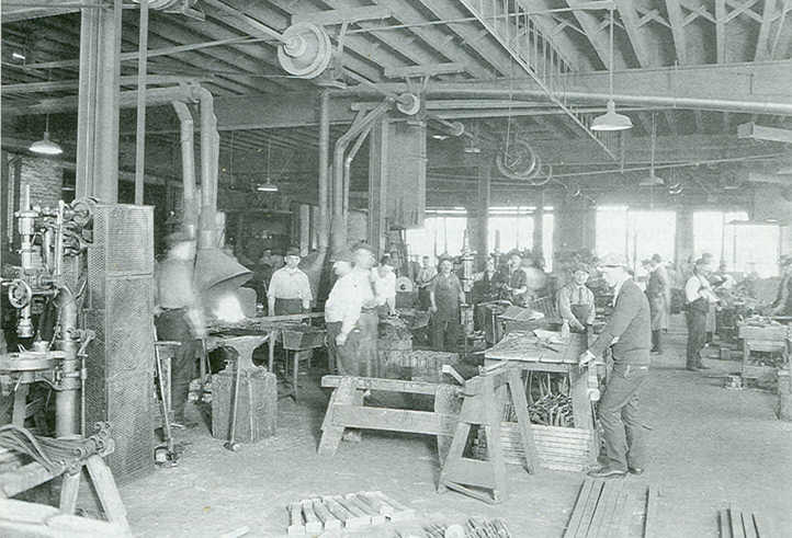
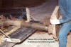
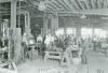 Photos
of shops from the late 19th century and early 20th century would be a good start.
At left is a photo found in the book Samuel Yellin ~ Metalworker by Jack Andrews,
ISBN 1-879535-05-X. The example is from a collection of photos of the Yellin
blacksmith shops from around the mid 1920s, and shows an excellent example of a
belt guard for a camelback drill. Look closely because the drill in the photo
looks very much like the Excelsior that is featured on this webpage.
Photos
of shops from the late 19th century and early 20th century would be a good start.
At left is a photo found in the book Samuel Yellin ~ Metalworker by Jack Andrews,
ISBN 1-879535-05-X. The example is from a collection of photos of the Yellin
blacksmith shops from around the mid 1920s, and shows an excellent example of a
belt guard for a camelback drill. Look closely because the drill in the photo
looks very much like the Excelsior that is featured on this webpage.
Don't limit the search however to only old photos. Sometimes current owners of
camelback drills build guards, so look also for photos and examples of camelback
drills used in modern shops.
A simple framework of angle iron filled in with expanded metal screen, will
serve as a good enclosure to prevent personnel from entangling in the belts and
pulleys and gears. Hinged at appropriate points to allow the screens to open for
easy access to oil and maintain the machine.
Buying and inspecting a drill.
xxxxxxxxxxxxxxxxxxxxxxxxx
Other websites featuring camelback drills.
W.F.&J. Barnes 20 inch drill
http://andy.sargent.net/boring/default.htm - Very nice drill. No back gears
but this drill has variable speed auto-down feed. Excellent motor mount for modern
motor.
Page updated
September 16, 2019
Attention stupid! Working with old
machinery is Not for amateurs! Due to the age
of these drills, most parts are unavailable and must be made by a competent
machinist. These drills are obsolete! Many of the original manufacturers
have gone completely out of business or have changed ownership and no longer stock
parts for the old drills. Buyer beware! You are on your own if you buy one of
these old drills. There are no longer any parts made for these drills. If you
break something, then you manufacture your own parts. If you have a problem with
making your own parts then DON'T buy one of these drills. Are you an idiot?
Are you too stupid to understand this? I can't help you if you buy a broken drill.
In fact I just don't care. If you buy one of these drills and it doesn't work and
you aren't skilled enough to figure it out on your own, then don't bother me
because I can't help you. These drills are for experts that can figure these
things out on their own. Not for morons that buy broken tools and expect everyone
else in the world to help them for free. If you have to ask me how to do it, then
you haven't got what it takes to repair one of these old drills.
Under construction
Page created February 02, 2004