[Home] [Back to Ye Old Drill] [Camelback Drills] [Morse Taper] [Standard No. 2 Chuck] [Westcott's Little Giant Chuck] [Jacobs Chucks] [The Post Drill] [Restoring Canedy-Otto No. 16]
Update September 3, 2008. Restoration work has been stalled for 9 years now. I am busy setting up and expanding my smithy and at the same time I am producing more metalwork. Repairs and restorations on this drill will continue when I have more time, possibly during the winter months late 2008-2009.
Here described is the beginning of a restoration to bring a very well made professional model hand powered drill press back to life. At the time of this writing the drill has been completely stripped down for cleaning and repair. More photos and updates will be added to this page later for those who have interest in repairing and restoring old machines and tooling. Click on thumbailed pictures to see full size.
The New No. 16 is a large heavy duty 2-speed combination hand-cranked and lineshaft driven drill press used by blacksmiths and machine shops from the end of the 19th century until the early part of the 20th century. It stands nearly 6 feet tall from the bottom of the pipe frame mount bracket to the top of the flywheel. This not counting that the drill must still be mounted a couple feet higher yet to allow the table and hand crank to be operated at a convenient height.
 This
drill was meant to run with or without power. If electrical, engine, or other
mechanical power was not available to the smith, he simply turned the hand crank
to run the drill by hand. Although I didn't have a copy of the manufacturers
catalog to verify drilling capacity of the this drill, I found an advertisement in
a competitors catalog depicting a similar drill and the manufacturer states their
drill is rated to drill a 1-1/2 inch hole. Drill weight is about 500 lbs.
This
drill was meant to run with or without power. If electrical, engine, or other
mechanical power was not available to the smith, he simply turned the hand crank
to run the drill by hand. Although I didn't have a copy of the manufacturers
catalog to verify drilling capacity of the this drill, I found an advertisement in
a competitors catalog depicting a similar drill and the manufacturer states their
drill is rated to drill a 1-1/2 inch hole. Drill weight is about 500 lbs.
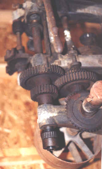
In the current photograph (top of page) taken before restoration was begun, the hand crank that allows the operator to run the drill by hand was removed. The large feed handle with its four handgrips imparts a semi modern appearance. And of coarse the dominating feature is the extra large flywheel above.
Flywheel, gear changes, ( update later )
The New No. 16 has two types of drill feed operation. The first is identical to modern drill presses involving a lever wheel fastened to the quill spline shaft, which engages the drill quill to force the drill spindle up and down. This is seen as the four large lever handles on the left side (user’s right) of the upper frame of the drill. When the drill is powered by belt to a motor or line shaft, the user need only loosen the ratchet clutch and run the feed lever wheel up and down to move the drill in the desired direction.
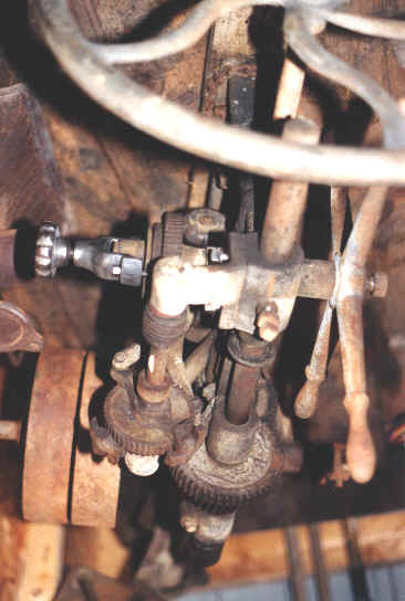
 Auto
feed is the second method of drill feed and is necessary when the user is cranking
the drill by hand and holding the work at the same time. Auto feed is accomplished
by lever action of a set of reciprocating arms, which rotate a ratchet wheel,
which in turn through a series of gears forces the quill shaft downward into the
work at a preset speed. Power for the lever arms is obtained by connecting them
through an eccentric gear attachment, which is driven directly by rotation of the
drill itself. The eccentric connection of the New No. 16 is adjustable via a large
thumb wheel which is loosened and slipped the desired length along the T-bolt slot
machined into the eccentric gear, allowing down feed speed to be changed by the
user.
Auto
feed is the second method of drill feed and is necessary when the user is cranking
the drill by hand and holding the work at the same time. Auto feed is accomplished
by lever action of a set of reciprocating arms, which rotate a ratchet wheel,
which in turn through a series of gears forces the quill shaft downward into the
work at a preset speed. Power for the lever arms is obtained by connecting them
through an eccentric gear attachment, which is driven directly by rotation of the
drill itself. The eccentric connection of the New No. 16 is adjustable via a large
thumb wheel which is loosened and slipped the desired length along the T-bolt slot
machined into the eccentric gear, allowing down feed speed to be changed by the
user.
 Down
feed pressure can be controlled during the auto feed operation by adjusting the
large thumbwheel on the clutch mounted to the quill spline shaft auto feed gear.
This feature which is not common on most other smaller presses, allows the
operator to gig the drill quill up or down by simply grasping the feed lever
handles and turning them even with the auto feed engaged. In comparison many
smaller hand crank drills require the operator to disengage the ratcheting feed
pawls and turn the feed ratchet wheel and screw by hand until the drill is finally
withdrawn. This feed clutch option also allows the New N0. -16 user to limit and
control the amount of automatic down feed force, however down feed force should
primarily be controlled by setting the correct speed position adjustment of the
eccentric gear T-bolt thumbwheel and auto-feed ratchet arm.
Down
feed pressure can be controlled during the auto feed operation by adjusting the
large thumbwheel on the clutch mounted to the quill spline shaft auto feed gear.
This feature which is not common on most other smaller presses, allows the
operator to gig the drill quill up or down by simply grasping the feed lever
handles and turning them even with the auto feed engaged. In comparison many
smaller hand crank drills require the operator to disengage the ratcheting feed
pawls and turn the feed ratchet wheel and screw by hand until the drill is finally
withdrawn. This feed clutch option also allows the New N0. -16 user to limit and
control the amount of automatic down feed force, however down feed force should
primarily be controlled by setting the correct speed position adjustment of the
eccentric gear T-bolt thumbwheel and auto-feed ratchet arm.
Two pulleys about 10-3/4 inches in diameter and 2-3/4 inches wide are mounted on the drill right (user left) side. The drive pulley is set-screwed directly to the drive shaft and is mounted closest to the drill frame. The drive pulley is rigidly mounted to the drive shaft so both rotate together. The idle or free pulley is mounted beside the drive pulley on the drive shaft but is not keyed or rigidly mounted to the shaft. The idle pulley can be turned freely so if the lineshaft belt is running, and the belt is shifted onto the idle pulley, the drive shaft will not be forced to turn while the idle pulley is spinning. When it is desired to operate a drill on a rotating line shaft, a weighted lever with lugs surrounding the drive belt is pulled so the belt lugs drag the drive belt over and onto the drive pulley. The drill will begin rotating. The idle pulley should be expected to begin rotating also after a few seconds of drill operation. When the user wants to stop the drill, the belt lever is pushed towards the idle pulley until the drive belt is positioned entirely on the idle pulley and after a few seconds friction will bring the drill to a stop.
The drill table is adjustable in height by rotating a crank handle, which rotates a jackscrew lifting, or lowering the table-mounting bracket. The table can be swung aside so large pieces can be handled in the drill. A hand screw tightens the table more securely to the frame after height is adjusted to desired level. Leveling screws beneath the table plate adjust the level of the drill table. The table can be removed entirely by removing the mounting clamp beneath the table plate. The table measures about 12inches square and has a hole in the center to allow the drill bit to pass. Slots are cut in the table like its modern day counterpart for the bolting and clamping of work.
 The
jackscrew pinion gear was seized to the shaft with rust and dirt. The pinion
assembly consists of a jackscrew, mount casting, crank pinion gear, and a shaft
threaded to the pinion mount casting. A washer riveted to the end of the shaft
secures the pinion gear to the end of the shaft. The opposite end of the shaft is
threaded into the jackscrew casting. A riveted retaining pin is placed through the
hole drilled through the casting and through the threaded end of the shaft to
secure the shaft to the casting. Without the retaining pin the threaded shaft
would unscrew itself from the casting due to friction.
The
jackscrew pinion gear was seized to the shaft with rust and dirt. The pinion
assembly consists of a jackscrew, mount casting, crank pinion gear, and a shaft
threaded to the pinion mount casting. A washer riveted to the end of the shaft
secures the pinion gear to the end of the shaft. The opposite end of the shaft is
threaded into the jackscrew casting. A riveted retaining pin is placed through the
hole drilled through the casting and through the threaded end of the shaft to
secure the shaft to the casting. Without the retaining pin the threaded shaft
would unscrew itself from the casting due to friction.
To remove the pinion gear, the shaft was threaded out of the mount casting after drilling and driving out the riveted retaining pin. This whole assembly was disassembled and cleaned and rubbed with emery cloth. The pinion gear was reinstalled on its shaft and a new pin riveted in place to secure the pinion shaft. A piece of 3/16ths cold rolled round was used to make a pin to rivet the shaft back in place.
The drill spindle is machined to take a 5/8ths inch round
shank drill bit or chuck arbor. A pawl positioned in the side of the drill spindle
in the form of a wedge presses into the flat side ground on the round drill shanks
or arbors so the drill has a positive grip on them to force them to rotate when
they encounter the resistance to drilling. A special nut and collar fitted to the
end of the spindle force the wedge inward to tighten it. Very small "ears" are
punched out of the sides of the angled surface ( too small to be visible in this
photo ) to catch the wedge and stop it from falling through the slot in the side
of the drill spindle.![]()
![]()
The 5/8ths inch round shank arbors can still be bought for now but this size is not interchangeable with the Morse taper parts for other drills, and 5/8ths inch shank drill bits are not available. So I have begun assembling an accessory kit to adapt the drill spindle to Morse taper accessories. A pair of Morse Taper extensions with 3MT shanks and 2MT and 3MT sockets, were sent to a machine shop to have the shanks turned down to 5/8ths inch round with a flat side. These extensions can be inserted in the spindle and Morse taper drills and chuck arbors can be used with this drill. I chose not to machine the drill press spindle to Morse taper so to preserve future historic value of the drill as a museum quality antique. Notice that the shoulder of the barrel of the extension is fitted closely to the bottom surface of the collet chuck. This I felt would add support to a weakened area of the extensions. The ends of the 5/8ths inch arbors must be fitted and cut closely to slide all the way into the collet of the spindle, yet not so short as to create a loss of contact area which supports the extension inside the drill spindle. As can be seen in the photo, the extensions can add considerable length to the drill spindle.
The chuck that came with the drill when I bought it was a Standard #2 Improved made by The Standard Tool Company of Cleveland Ohio. This is a large old fashioned style chuck as seen in many antique advertisements from the turn of the century. It will take straight shank bits from 1/16th to 3/4th of an inch. Follow this link for more on this chuck.
The crank handle which rotates the drill spindle was straightened and untwisted. A new wooden grip was made to fit onto the crank handle to replace the missing wooden grip. The old one had worn off years ago. An example of the handle to be copied was from the New no. 16 drill that can be seen in the blacksmith shop in Dows Iowa. This is the style of handle which I had copied for my own drill spindle crank handle. The crank for the height adjustment on my drill is missing. A "new" table height crank may be purchased or possibly made by me at a later date when the drill restoration is completed. The photo to the right is of that drill.Where's the crank handle?
About the Dows Drill example. The drill at the Dows blacksmith shop, was converted long ago into an electric only drill press with a motor mounted on the top rear of the frame. They also made a pedestal frame stand to mount their drill like a regular modern drill press. The handle that was still on their drill was the crank which adjusts the height of the table. The Dows shop was a town blacksmith shop which also built wagons during the early part of the 20th century. A line shaft once ran many of the tools in this shop.
Current restorations actions taken:
The initials JT refer to Jacobs Taper, which is a standard type of taper used in mounting drill chucks to arbors. MT refers to Morse Taper which is a standard machine taper often used for accurately centered mandrel and socket type fittings such as fitting drill arbors to drill spindle sockets and lathe centers and tail end tools. An "arbor" is a mandrel to which a drill chuck is fitted, and with which the chuck can be mounted to the drill press Spindle shaft. When a Morse taper drill arbor is pressed into a drill spindle, friction is strong enough to hold it there until pried apart with a wedge.
There is still a lot more work to be done before the drill can be reassembled
and a stand built and mounted. More updates will follow as work progresses.
Photos of completed work will be added later.
Latest Update August 2nd, 2003.
Readers who have knowledge or documentation concerning professional inspection and repair of this drill are invited to mail the author at the email address below. NOTE: this does not include silly little sales advertisements from old magazines or catalogs. I am looking for real information concerning maintenance inspection and repair. A mechanic's service manual must have existed at one time for the higher priced heavy duty drills sold by the Canedy Otto company but I haven't been able to locate one yet.
The author can be emailed at address in picture below: